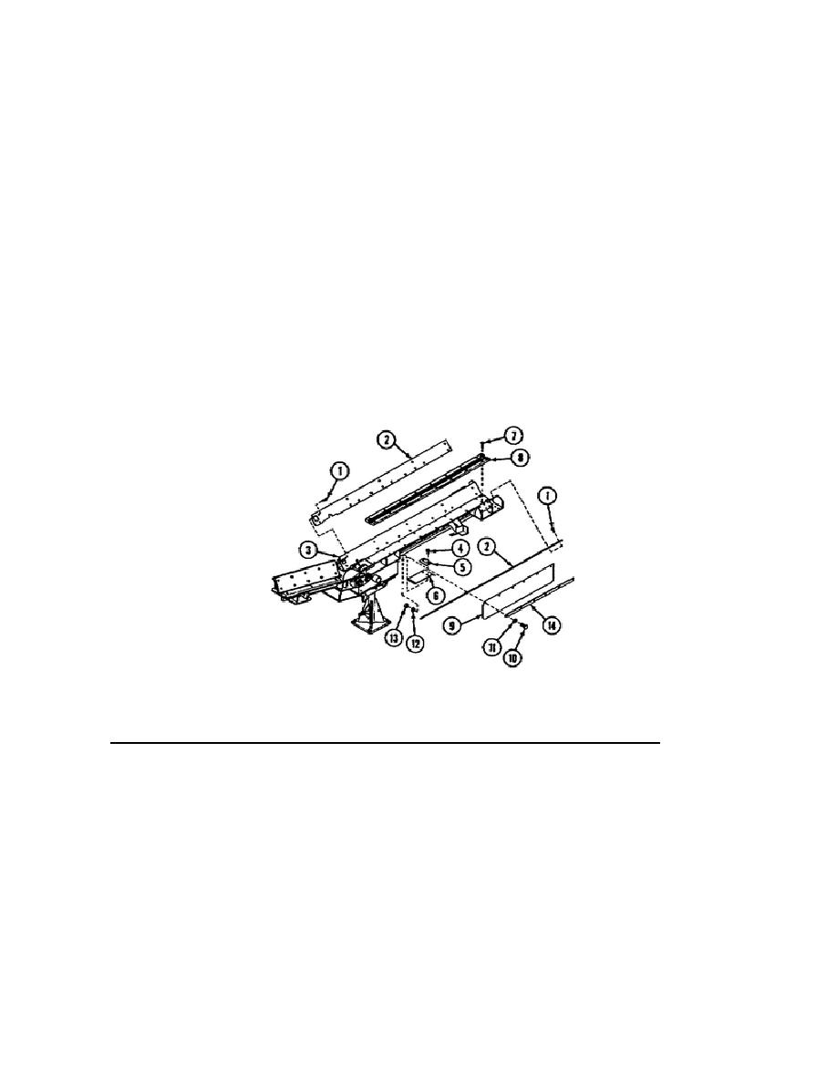
o Remove the two screws (4), chain return wear strip (5), and spacer (6) from
the conveyor section.
o Remove the sixteen screws (7) and the bottom wear strip (8).
o Remove the chain guards (9) by removing six screws (10), flat washers (11),
lockwashers (12), nuts (13), and retaining strip (14) from each chain guard.
The installation procedure is accomplished following the steps outlined:
o Thoroughly clean the wear strip mounting surfaces of the drive end section
(3) with solvent (Item 19, Appx. D) and clean, dry rags (Item 50, Appx. D).
Ensure all particles are removed.
o Roughen the underside of the wear strips (2). Apply adhesive (Item 4, Appx.
D) to the roughened side of the wear strips and mounting surfaces of the
drive end section (3). Allow the adhesive to dry tacky before installation.
Apply sealing compound (Item 53, Appx. D) to the threads of the screws (1).
o To complete the installation process, reverse the removal process.
Figure 23.
Drive End Section Wear Strips.
21. Removal and Installation of the Conveyor Assembly and Support Stand.
Prior to beginning this maintenance procedure, ensure that all systems are shut
down and the MASTER switch is in the OFF position.
If the hydraulic system has
been in operation
29
OD1737


 Previous Page
