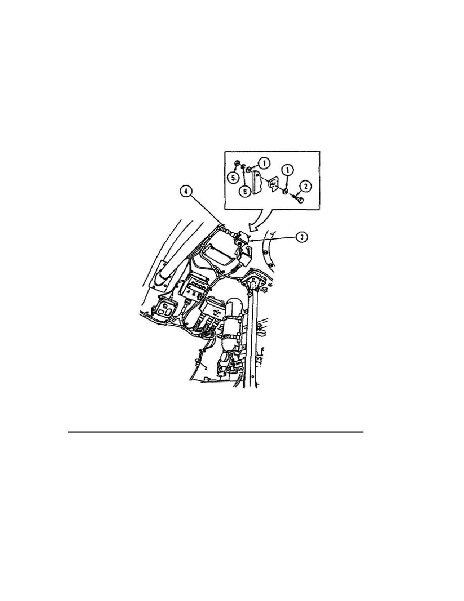
o The engine AFES is deactivated. You must now disconnect the wiring
harness plug (Item 4) from the RSI (Item 3).
o Supporting the RSI, remove two nuts (Item 5), two lockwashers (Item
6), four flat washers (Item 1), and two screws (Item 2) which secure
the RSI to the ceiling bracket. Now remove the RSI and discard the
removed lockwashers.
o Installation of the engine
AFES
RSI
is
accomplished
using
the
reverse order of removal.
Figure 32.
Engine AFES Remote Status Indicator.
9.
AFES Electrical Wiring Harnesses - Removal and Installation.
During this portion of the subcourse, you will learn the procedures involved
in the removal and installation of the AFES electrical wiring harnesses. TM
9-2350-267-20 illustrates the difference in wiring harness numbers between
vehicles 1 through 344 and vehicles 345 and above. You need not review the
technical manual for completion of this subcourse.
Some difference also
exists in the removal and installation procedures.
For purposes of this
subcourse, all instructions related to AFES electrical wiring harness
removal and installation will pertain to vehicles 1 through 344.
50
OD1700


 Previous Page
