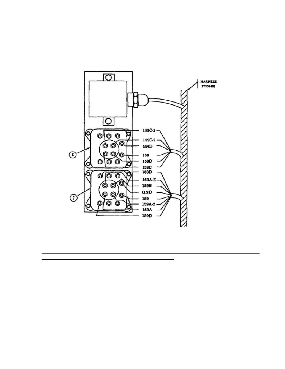
REMEMBER, there are six wires connected to the middle relay and eight wires
are connected to the bottom relay. Using Figure 29 and the reverse of the
removal procedures, install the components which were removed in the removal
process. Be sure you install new lockwashers. When you have installed all
components, turn the engine T/A panel MAINTenance switch to the horizontal
position.
Figure 29.
Engine AFES Relays - Installation.
8.
Test Alarm Panels. Standard Control Electronic Amplifier, and Remote
Status Indicator - Removal and Installation.
This portion of the subcourse will teach you how to remove and install the
engine and crew AFES T/A panels, the SCEA, and the RSI.
The removal and installation of the engine T/A panel will be the first of
four items addressed during this process. Using Figure 30 to identify the
engine AFES T/A panel components and the removal procedures shown below,
begin the process of removing the engine AFES T/A panel.
46
OD1700


 Previous Page
