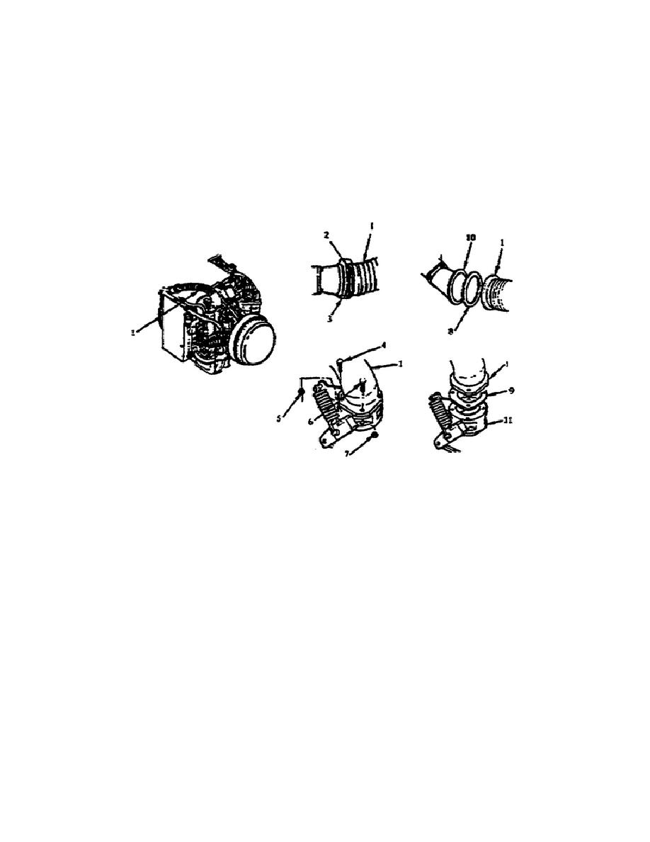
self-locking nut (2) and the grooved clamp coupling (3) from the
tube (1). Then, remove the bolt (4) and self-locking nut (5) from
the tube.
Next, remove the three bolts (6) and self-locking nuts
(7) from the other end of the tube (1) (fig 1-6).
You can now lift the end of the tube and remove the bleed air gasket
(8).
Now, lift the tube and remove the other gasket (9) and the
tube assembly from the powerpack. After you have removed the tube
assembly, cover the two bleed valve openings (10 and 11) with
chipboard and tape, to keep dirt, moisture, and other objects out of
the engine (fig. 1-6).
Figure 1-6.
Compressed Air Tube Assembly.
Remove the Accessory Gearbox Vent Hose.
To remove the accessory
gearbox vent hose, you must loosen the two clamp screws (2) on the
hose (1) and pull the hose from the fittings (3 and 4).
Then,
remove the clamps (5) from the hose (fig. 1-7).
Remove the lubricating Oil Tank Assembly. To remove the lubricating
oil tank you must have removed the following components (TM 9-2350-
264-20-1-3):
-- Upper side airflow baffle.
-- Lower side airflow baffle.
-- Ignition exciter.
Once you have completed the tasks above, remove the P8 plug (1) from
the oil dual level float switch (5). Then remove the screw (6) and
self-locking nut (7) from the
7
OD1707


 Previous Page
