the oil tank and gearbox module (LO 9-2350-264-12).
Dispose of the
used oil according to local policy.
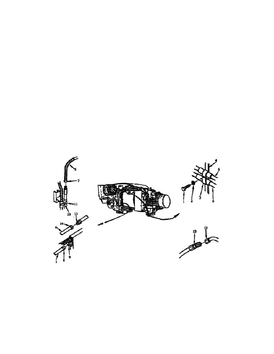
Remove the Oil Cooler Inlet and Outlet Tube Assembly (Right Side).
Before you can remove this tube assembly, must establish the correct
equipment condition by removing the lower side air baffle and the
upper side cable duct.
With the correct equipment condition
established, start the removal process by removing the screw (1),
washer (2) and strap (3) from the bracket (4). Then place a pail
under the coupling nut (7).
With the pail in place under the coupling nut, unscrew the nut (7)
on the outlet tube (5), and unscrew the nut coupling nut (8) from
the oil filter assembly (9).
Remove the outlet tube from the
powerpack.
To remove the inlet tube (6), loosen the screw (10) on the clamp
(11) and place the pail under the coupling nut (12). At one end of
the inlet tube unscrew the coupling nut (14) from the nipple (13),
and at the other end of the tube unscrew the coupling nut (14) for
the other nipple (15).
Remove the inlet tube from the powerpack
(fig. 1-1).
Figure 1-1.
Oil Cooler Inlet and Outlet Tube
Assembly (Right Side).
Remove the Hose Assembly (Oil Tank Vent). To remove the vent hose
assembly, remove the four long screws (2) and lockwashers (3) from
the spacer (4). Then, you must
3
OD1707


 Previous Page
