f. Laser Pulse.
(1) Arrange the test setup as shown in figure 1-21.
(2) Set the MODE switch (figure 1-9, item 17) to 1 TGT.
(3) Make the electrical connections shown in figure 1-22, part
C.
(4) The waveform shown in figure 1-22, part C appears
momentarily when the LR is fired.
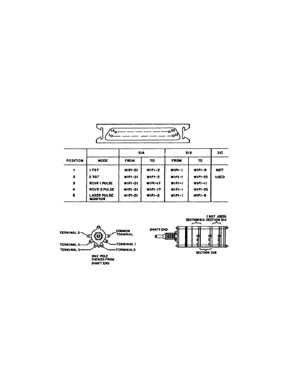
Conduct continuity checks of the MODE switch/Plug W1P1 (figure 1-11,
items 10 and 11).
Only two (S1A and S1B) of the three wafers are
used (see figure 1-23). A full test of the switch requires that you
check all five rotary positions.
The measurements for the MODE
switch are shown in figure 1-23.
Figure 1-23.
MODE Switch S1/Plug W1P1.
2.
Testing and Troubleshooting.
Testing of the LR Test Set consists of a procedural visual inspection
and a pass/fail test (operational check).
When you detect a
discrepancy during visual inspection, you must take the proper
corrective action, as specified in this lesson.
This action may
consist of the following:
31
OD1716


 Previous Page
