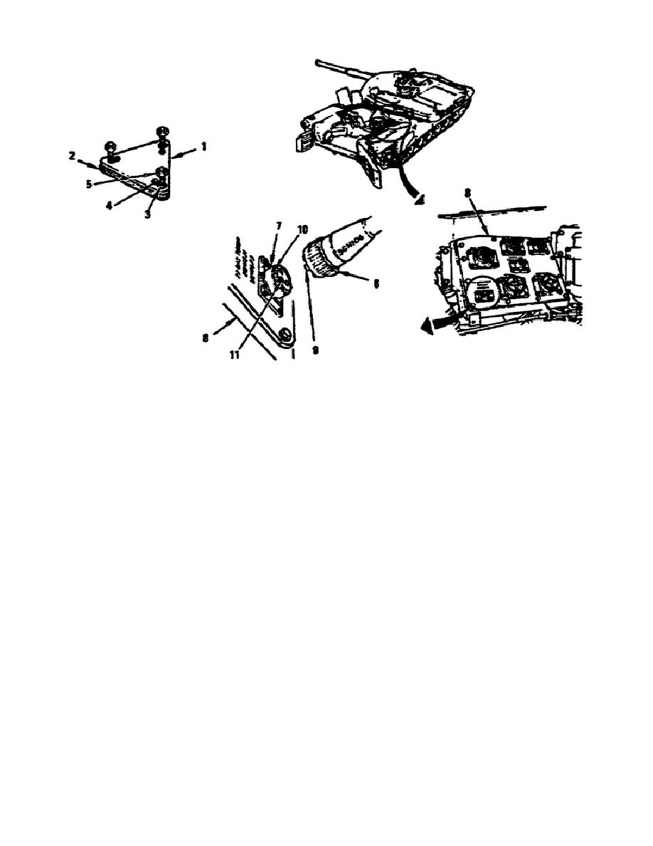
Figure 1-24.
Cable Connections and Hydraulic Test Cover.
b. Install the Ground Hop Cables.
Only one plug connector (6)
fits each panel connector (7).
You must match the numbers on the
plug connectors with the numbers printed above the panel connectors.
If you find an identification label or number missing, carefully
match the number and position of the pins (9) in the plug connector
(6) and with holes (11) in the panel (fig. 1-24). When installing or
matching the cables, remember engine cables numbers start with 3W,
ground hop cable numbers start with 3GH, and the panel cables
connector numbers start with 2W.
When installing the cables, one soldier makes the connection at the
powerpack while another soldier makes the connection at the panel.
You remove and install the protective caps as necessary to install
the cables. However, make sure that all the connections requiring a
protective cap have one in place unless you connected a cable to the
connector. You install the ground hop cables using the steps below:
NOTE:
All call-out numbers for the procedure below refer to figure
1-25.
Connect the T7 gas temperature plug connector 3W106 (4) to
cable 3GH106 (1), and connect the other end of the cable to
the receptacle connector 2W115 (5) on the control panel
(6).
28
OD1709


 Previous Page
