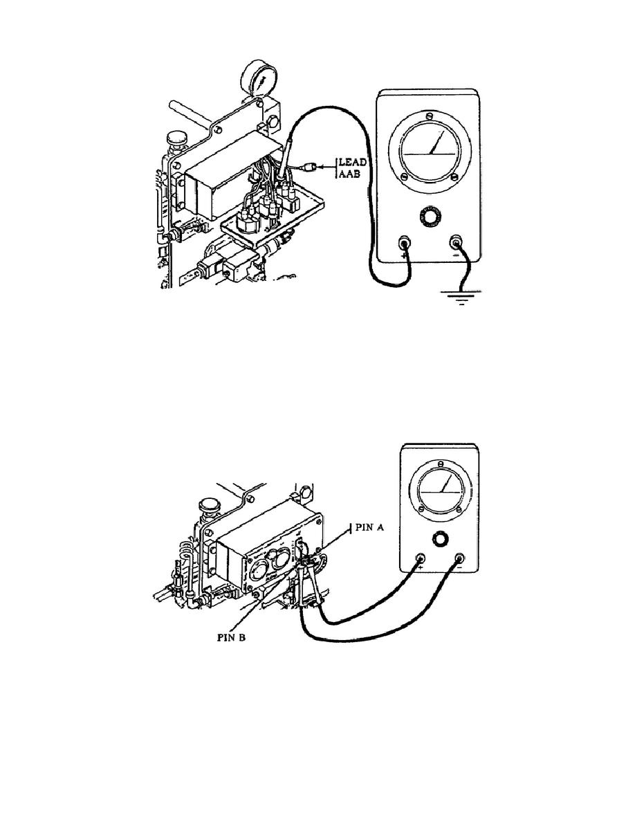
Figure 35.
Lead AAB Test Point.
o Disconnect the gage panel connector. Check the continuity with a multimeter
by placing the red probe on connector pin A and the black probe on pin B of
the hydraulic gage panel mounted connector (Fig. 36).
Place the conveyor
control switch to the IN position.
If the multimeter remains on infinity,
lead AAA between the conveyor control switch and the hydraulic control panel
must be replaced.
However, the multimeter indicated 0 ohms and you must
continue to troubleshoot the system.
Figure 36.
Continuity Test, Lead AAA.
o Place the red probe on connector pin C and the black probe on pin B of the
hydraulic gage panel mounted
40
OD1737


 Previous Page
