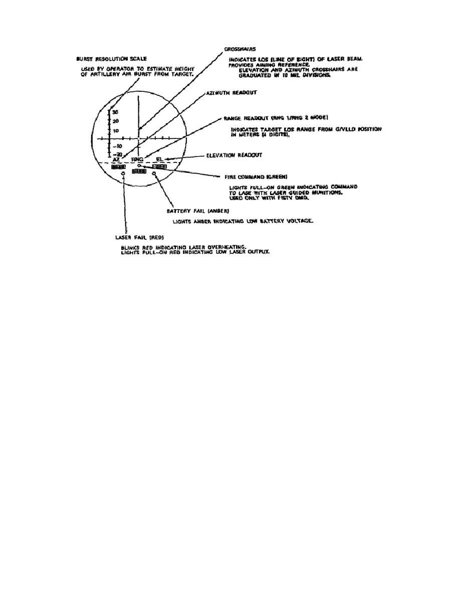
Figure 1-10.
LD/R Eyepiece Display.
The FIRE COMMAND light (green)
is in the lower middle of the display,
just above the RNG readout.
The FIRE COMMAND indicates an external
command to fire the laser when
used for designating targets for laser-
guided ordnance.
You receive
the command through the digital message
device.
Finally, the BATTERY FAIL light (amber) at the lower right of the
display, indicates that the battery voltage is low.
Also located on the exterior of the LD/R are four electrical connectors.
The test access connector (1J1) provides a troubleshooting capability by
connecting the LD/R to the fault locator.
The TU connector (1J2)
interfaces the TU and the LD/R to provide power to the TU and to allow
azimuth and elevation data to be transmitted to the LD/R.
The DMD
connector (1J4) allows you to connect the DMD to establish communications
with TACFIRE, or other external positions.
The DMD connector is also
used for testing. The FIST connector (1J7) links the G/VLLD with the
Fire Support Team (FIST) and provides troubleshooting using the remote
capabilities tester (RCT).
When you remove the battery from the LD/R, you find another connector
exposed.
This connector (1J3) mates with the EMI filter to use an
external power source for operating the G/VLLD. To remove the battery,
pull the battery release pin located below the FIST connector.
14
OD1721


 Previous Page
