(4) If operational temperature is greater than 40 F.
The
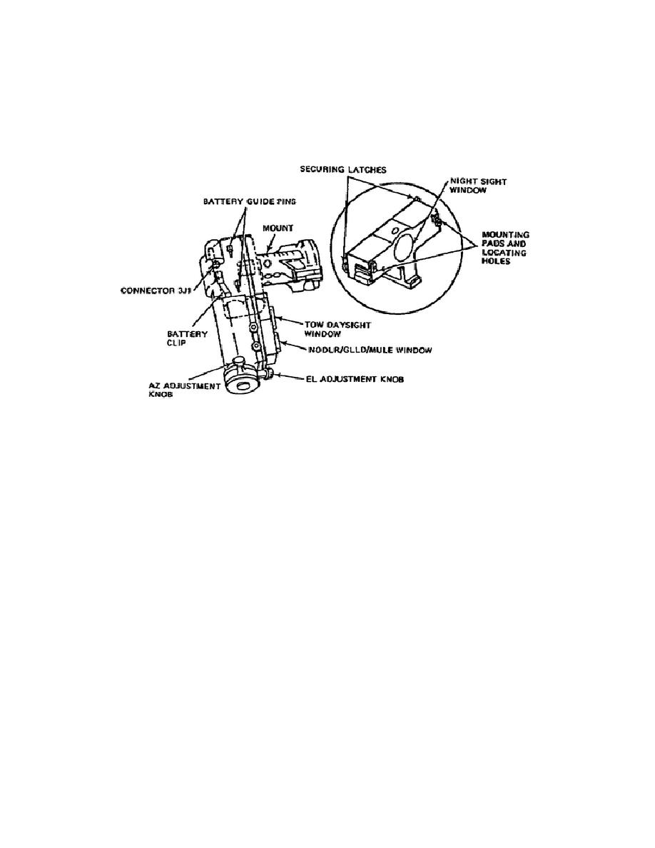
boresight collimator has a mounting surface that allows you to install
the battery (see figure 1-13). It also has EL and AZ adjustment knobs to
adjust the collimator reticle. Also located on the boresight collimator
are the optical windows that provide the optical path for the collimation
sequence.
Figure 1-13.
Boresight Collimator Controls.
PART B - FUNCTIONAL OPERATION OF
COMPONENTS AND ASSEMBLIES OF THE G/VLLD
As a fire control systems repairer, you perform the maintenance necessary
to keep the G/VLLD operating at peak performance. To do so, you must
understand the operation of the system. In part A of this lesson, you
identified the major components of the G/VLLD set and located the
controls and indicators you use in system operation and maintenance. In
this part of the lesson, you identify the components and assemblies
within the major components, and see how they function together in the
operation of the system.
Appendix B provides a set of functional diagrams of the G/VLLD system.
These diagrams are copied from TM 9-1260-477-34-2. Figure FO-17 shows a
block diagram of the system functional operation. Refer to this diagram
during the description of the functional operation process. The diagram
divides the operation into six major functions: (1) the power supply,
(2) the transmitter, (3) energy control, (4) the receiver, (5) display,
and (6) control logic/microprocessor.
All components and signals are
within the LD/R unless otherwise noted.
18
OD1721


 Previous Page
