

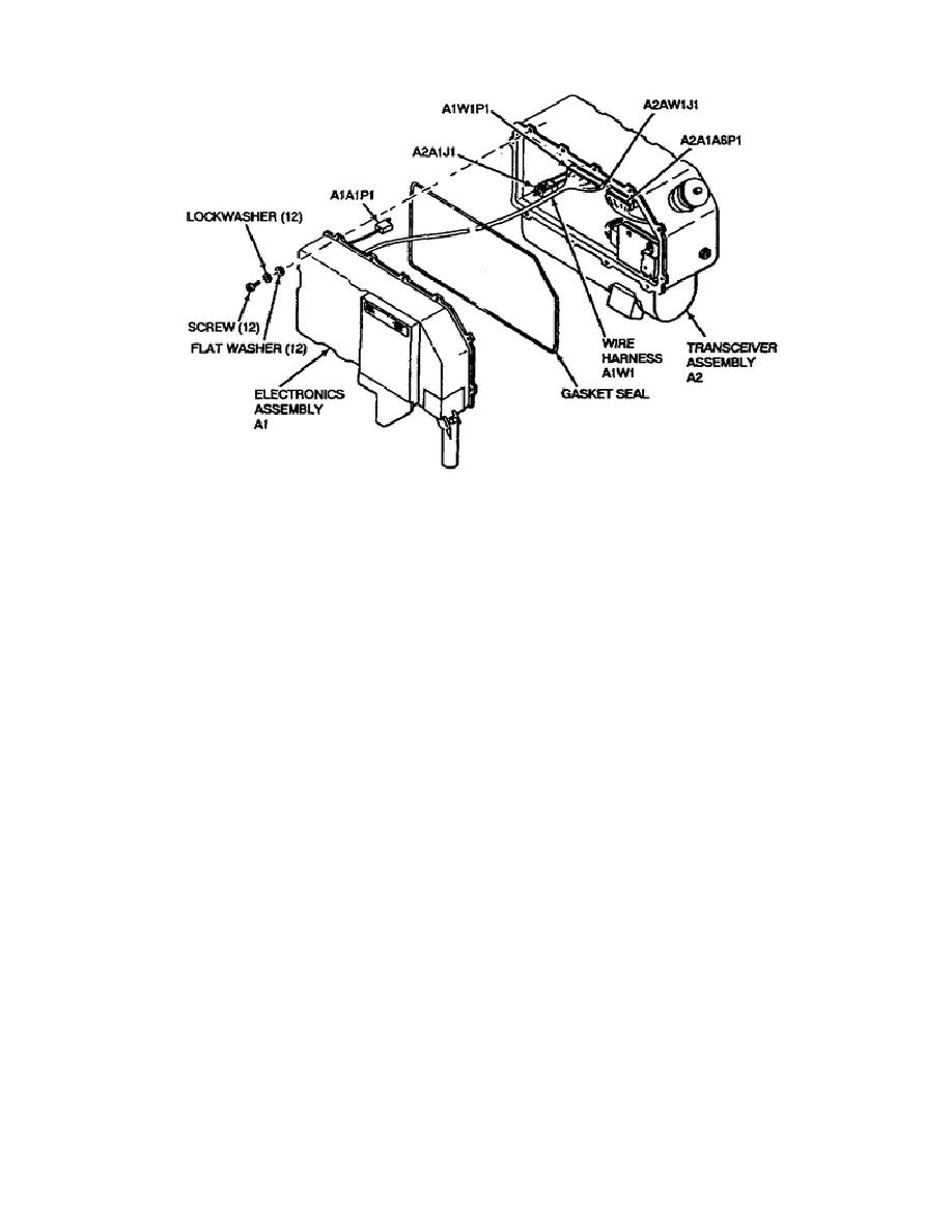
Figure 1-14.
LD/R Subassemblies.
a. Power Supply Function (figure FO-18 of appendix B).
Operating
power for the G/VLLD comes from the 24 V battery, or from external power
supplied by the vehicle through the EMI filter. The +24 V power enters
the LD/R through connector pin 1J5 and returns through pin 1J3. The +24
V go to the POWER switch AlW251, and to the pulse forming network (PFN)
power supply.
With the POWER switch set to ON, the +24 V supplies five different
functions:
(1) power to the PFN, (2) power to the FIST controls (if
used), (3) power to the display test mode through relay K1, (4) power to
the TRIGGER switch, that when pulled, energizes the low voltage power
supply (LVPS) to turn on the LD/R electronics, and (5) power to the
RETICLE BRIGHT potentiometer AlW2R1 to illuminate the reticle.
The mode switch A1W2S2 outputs two control signals, LDR DES/RNG and LDR
RNG1/RNG2. The LDR DES/RNG signal goes through the power supply card to
the microprocessor U9 in the control logic card A1A2 to place the LD/R in
the designate or the rangefinder mode.
Similarly, the LDR RNG1/RNG2
signal goes through the power supply card to the range counter U16 in the
control logic card to put the range counter in either the RNG1 or RNG2
mode.
The power supply card A1A1 contains the LVPS, the simmer power supply,
and the PFN power supply. Their outputs distribute throughout the system
to perform the required functions.
20
OD1721

 Previous Page
