direction of the hydraulic motor by the conveyor directional
control valve. Control rotational speed of the motor by setting
the flow control valve (Fig. 2F).
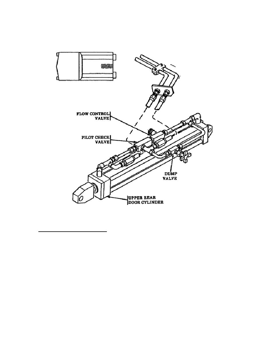
Figure 10. Upper Rear Hydraulic Actuators
and Related Components.
5.
Hydraulic Control Panel.
This panel contains the valves, gages, and other components used to
control the hydraulic system.
Refer to Figure 2F for a visual
perspective of the panel.
The following paragraphs describe the
hydraulic control panel components:
o Main Pressure Relief Valve - limits the pressure of the hydraulic
system to a maximum of 1550 psi. If system pressure exceeds the
1550 psi setting, it will be relieved through the valve back to
the hydraulic reservoir.
o System Pressure Gage - monitors hydraulic system pressure.
11
OD1703


 Previous Page
