maximum (Fig. 3F). This pressure, held by a check valve, engages
the backup system clutch, which activates the belt-driven backup
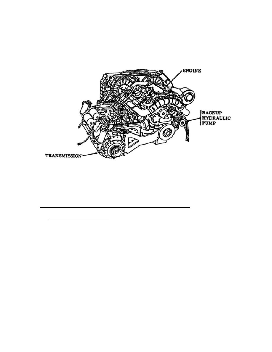
pump mounted on the main engine (Fig. 4).
The engine-mounted
hydraulic backup pump delivers 7.1 gpm of flow at a system
pressure of 1550 psi with the engine operating at 1100
revolutions per minute (rpm).
Figure 4.
Backup Hydraulic Pump.
To disengage the backup hydraulic system pump, open the pressure
release check valve to release hydraulic fluid pressure, and push
the selector valve in.
This will allow the primary hydraulic
pump to provide the hydraulic fluid for system operation.
3.
Subsystems of the Primary/Backup Hydraulic System.
o The Conveyor System.
The conveyor is a hydraulically powered
system that can be operated in either the forward or reverse
direction (Fig. 5F). Use two stationary dead-end sections, one
at each end, as staging areas for ammunition transfer.
The
powered or moving parts of the conveyor are: drive end, center,
and take-up end sections.
A three position switch, located in the hydraulic control panel,
actuates the solenoids attached to the conveyor directional
control valve which allows the conveyor motor to operate in
either forward or reverse. A drive sprocket coupled to the motor
shaft moves the conveyor chain.
An override safety (ON/OFF)
switch, located at
6
OD1703


 Previous Page
