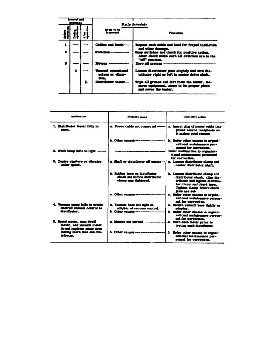
Figure 7.
Preventive maintenance checks and services.
Figure 8.
Troubleshooting.
(3) Place voltmeter INT-EXT switch in INT position.
(4)
Place ammeter IN-OUT switch in IN position.
(5) Place CIRCUIT BREAKER in ON position.
(6) Place VOLTAGE SELECTOR switch in 6V, 12V, or 24V position.
(7) Place CIRCUIT SELECTOR switch in A position.
OS 010, 8-P11


 Previous Page
