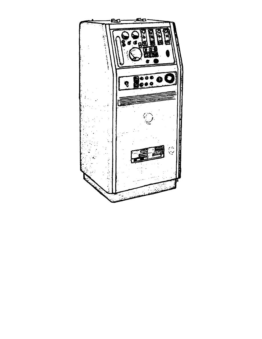
Figure 10.
Model HT-1 heater test set.
(12) Connect a Jumper wire from pin C of receptacle A to pin A of
receptacle A. Indicator light A should remain illuminated when switch A is in HI,
LO, and OFF positions.
(13) Connect a Jumper wire from pin C of receptacle A to pin B of
receptacle A. Indicator light A should illuminate only when switch A is in HI or
LO position.
(14) Connect a Jumper wire from pin C of receptacle A to pin D of
receptacle A. Indicator light A should illuminate only when switch A is in HI
position.
(15) Place CIRCUIT SELECTOR switch in B position.
(16) Place test set switch B in RUN position.
Fuel pump should operate
only when switch is in this position.
OS 010, 8-P13


 Previous Page
