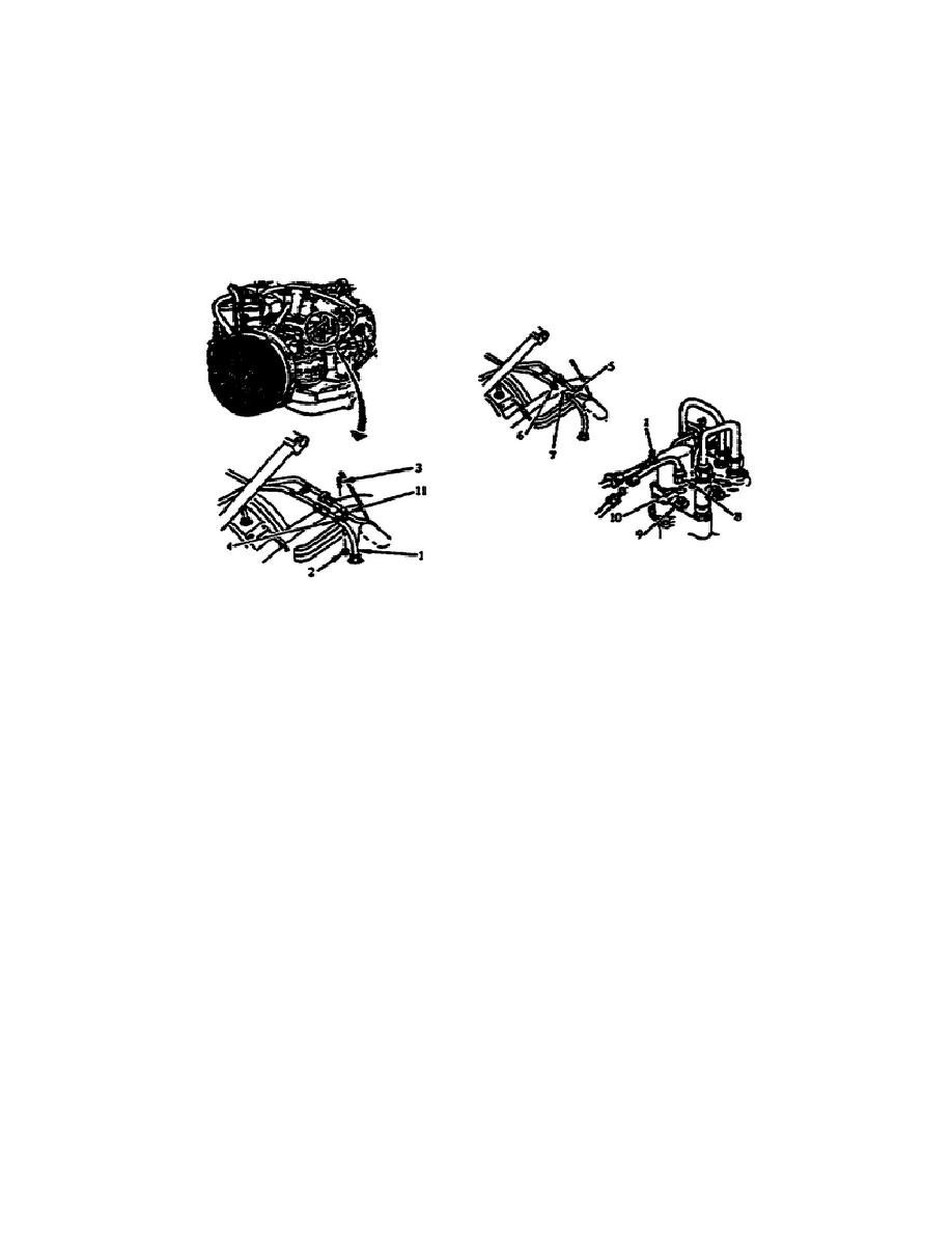
Remove the Tube Assembly (Electromechanical Fuel System to the Top
of the Inlet Guide Vane Actuating Cylinder).
Remove the self-
locking nut (2) and screw (3) from the loop clamp (4 and 11) and
remove the clamp from the tube (1). Then, you disconnect the tube
nut (5) from the adapter (6) and remove the flared conical seals
(7). At the other end of the tube Assembly, disconnect the tube nut
(8) from the adapter (9), lift out the tube assembly, and remove the
flared conical seal (10) (fig. 1-33).
Figure 1-33. Tube Assembly (Electromechanical Fuel System
to the Top of the Inlet Guide Vane Actuating
Cylinder Tube Assembly).
Remove the Main Hydraulic Centrifugal Pump. Before you can remove
the main hydraulic centrifugal pump you must disconnect the
hydraulic quick-disconnect coupling halves and an electrical
connector.
NOTE:
The electrical connector (1) may be located as shown on the figure,
or may be located between the two coupling halves (2) on the pump
(3) (fig. 1-34).
To remove the hydraulic quick-disconnect coupling halves (2 and 4)
you must first loosen the four screws (6). Then pull back on the
collars of the three coupling halves (4 and 5), turn them
counterclockwise, and lift them from the mating coupling halves.
After you have disconnected the quick-disconnects, remove the
electrical connector (1) from the pump (3) (fig. 1-34).
NOTE:
Hold the pump upright at all times so fluid does not pour out.
26
OD1707


 Previous Page
