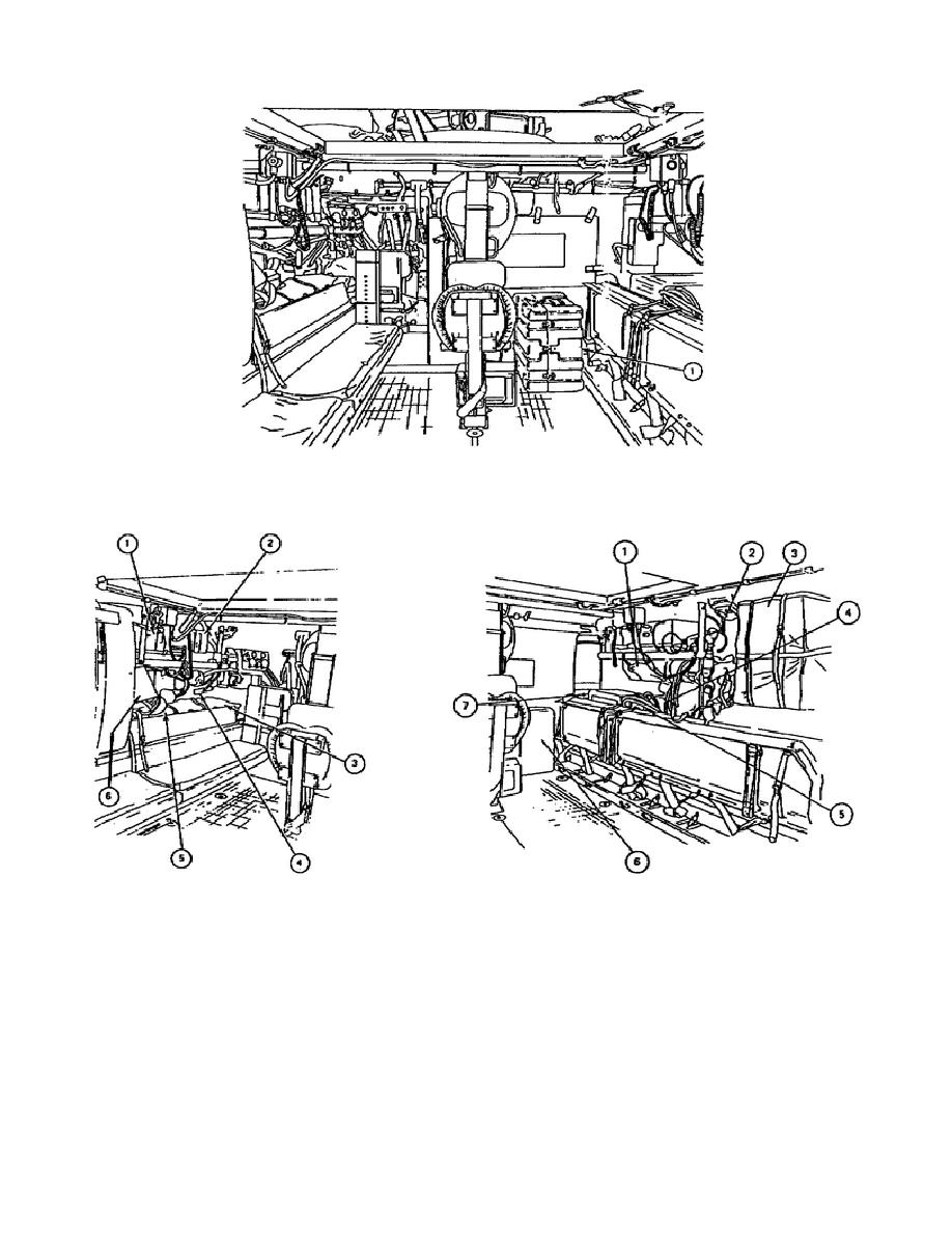
Figure 1-22.
M1/3A1 Front Wall.
Figure 1-23.
M1/3A1 Left
Figure 1-24.
M1/3A1 Right
Side Wall.
Side Wall.
(2) Refer to figure 1-26.
On the vehicle adapter assembly, push the
locking handle (3) ccw to release the lock.
With one hand on the locking handle
and the other hand on the adapter assembly, move the adapter assembly up and down
and sideways until the bubble (2) inside the precision level (1) is roughly
centered within the ring.
Push the locking handle cw until the vehicle adapter
assembly is locked in place.
26
OD1720


 Previous Page
