

the flywheel and serves as a support for the starter motor and
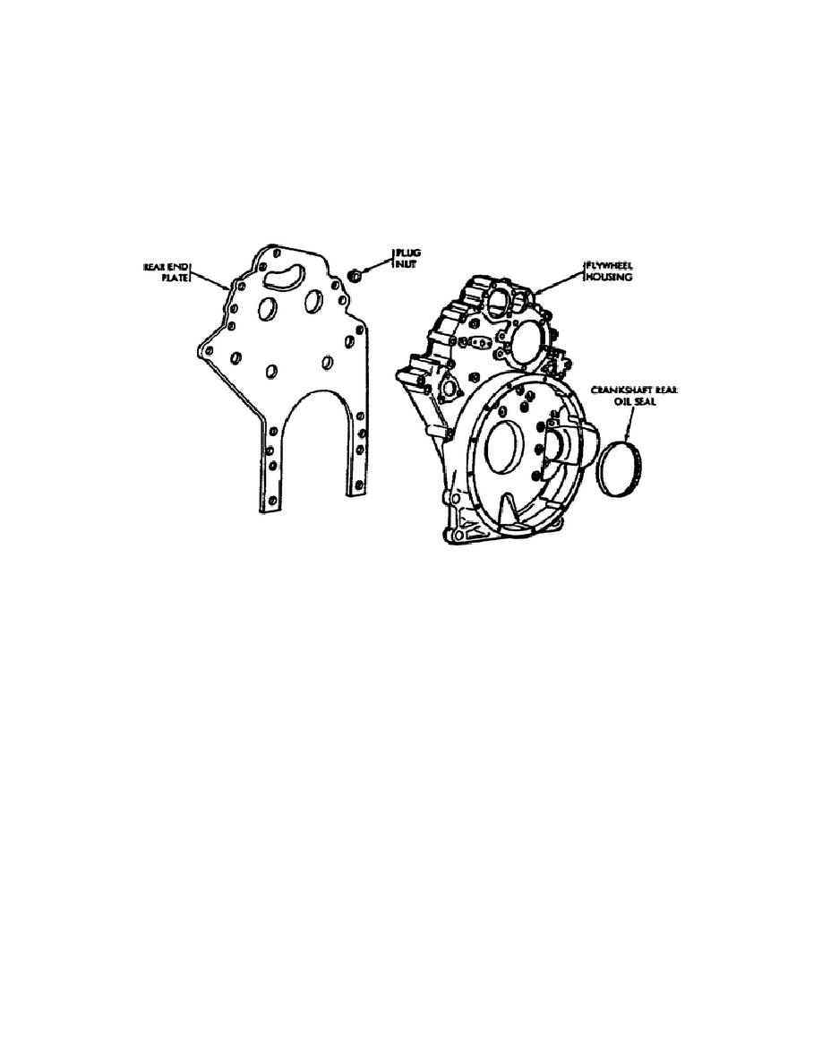
transmission. You can remove or install the crankshaft rear oil seal
without removing the flywheel housing.
j. The Cylinder Block End Plate (Fig. 9). This is a steel plate,
bolted to the rear of the cylinder block, that serves as means of
mounting the flywheel housing. At the time of engine overhaul or of
a cylinder block change, you must remove the end plate.
Figure 9.
Flywheel Housing and Rear End Plate.
k. The Oil Pan (Fig. 10). The oil pan is a one-piece, cast iron,
deep sump oil pan attached to the block using a one-piece gasket to
seal the pan.
The oil level gage rod tube attaches to the side of
the oil pan.
l. The Camshafts (Fig. 11). Four bushing type bearings, located
near the top of the cylinder block, support the camshafts.
They
actuate the valve and injector operating mechanisms for each cylinder
head. Heat treating of the individual operating cams provides a hard
wearing surface.
The end bearings receive pressure lubrication.
From the end
bearings, the oil feeds through an oil passage in each camshaft to
the intermediated bearings. A key and nut secure the balance weights
by a nut on one end of each camshaft. The balance weights (pulleys)
mount on the front of each camshaft.
The helical camshaft gears,
mounted on the rear of each camshaft, mesh with each other and are
driven from the crankshaft timing
14
OD1713

 Previous Page
