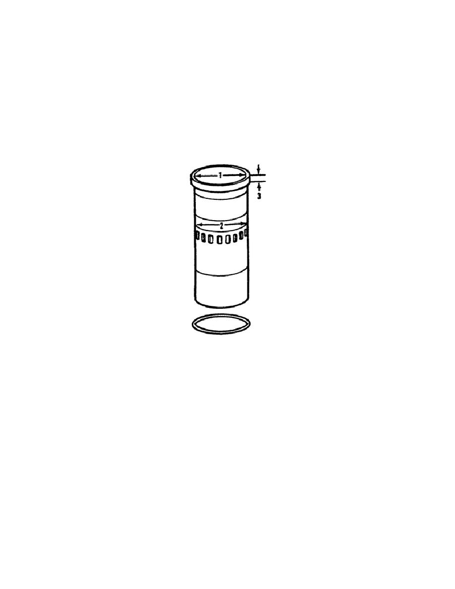
ring, recessed in the cylinder block bore between
the
liner
and
block, prevents water from leaking into the air box.
The liner's upper portion receives cooling from the water surrounding
it.
The center section of the liner receives cooling from the
scavenging air entering the cylinder through the 18 equally spaced
ports in the liner. The water inside the cylinder block water jacket
surrounds the liner's lower portion, thereby cooling it.
The angle
of the inlet ports, in the cylinder liner, creates a uniform swirling
motion with the intake air as it enters the cylinder.
This motion
persists throughout the compression stroke and facilitates scavenging
and combustion.
Figure 6.
Cylinder Liner.
c. The Crankshaft (Fig. 7).
The crankshaft is one-piece, heat
treated, and steel forged with all main and connecting rod bearing
journals and oil seal surfaces induction-hardened.
Counterweights,
incorporated in the crankshaft, ensure complete static and dynamic
balance.
Thrust washers, at the rear main bearing cap, control the
end thrust of the crankshaft.
All connecting rod and main bearings
receive lubrication, under pressure, through drilled passages in the
crankshaft and block. A press-fit timing gear is on the rear of the
crankshaft, and a press fit oil pump drive gear is on the front of
the crankshaft.
d. The Flywheel and Adapter Plate (Fig. 7). Attached to the rear
of the crankshaft is the flywheel.
Six bolts and a scuff plate,
between the flywheel and bolt heads to prevent the bolts from
damaging the flywheel, secure the flywheel to the
10
OD1713


 Previous Page
