M2/M3 BFV: FIRE SUPPRESSION SYST - OD1607 - LESSON 2/TASK 2
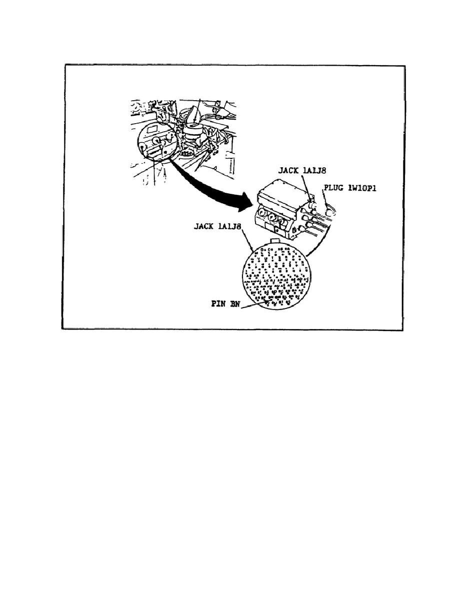
FIGURE 32.
THE VEHICLE DISTRIBUTION BOX.
(c) Using a multimeter, PFC Elrond measures the voltage
between jack 1A1J8 pin BN and ground.
If 20 or more volts are
present, he must replace wiring harness 1W10. However, he obtains a
reading of only 16 volts.
(d) PFC Elrond now knows that the problem is in the vehicle
distribution box.
He replaces the vehicle electrical distribution
box following the procedures outlined in TM 9-2350-252-20-1-3. When
the replacement is completed, he verifies that the problem has been
solved by repeating the initial tests and performing the procedures
in pathway one if STE-M1/FVS test 67 registers less than 20 volts.
e. Pathway Three.
Another troubleshooting pathway that can
isolate a defective component within the fire suppression system
develops when the initial test results are: test number 67 reads more
than 20 volts; the gage pressure readings on both squad
48


 Previous Page
