

M2/M3 BFV: FIRE SUPPRESSION SYST - OD1607 - LESSON 2/TASK 2
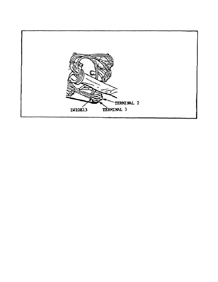
FIGURE 31.
FIRE SUPPRESSION SWITCH TERMINALS.
(3) Having received a reading of less than 20 volts, PFC Elrond
next uses the multimeter to measure the voltage between FIRE
SUPPRESSION switch terminal 2 (refer to figure 31) and ground.
He
knows that a reading of more than 20 volts means that the FIRE
SUPPRESSION switch is causing the trouble.
However, he finds that
the reading is less than 20 volts.
(4) Having obtained a reading of less than 20 volts between
terminal 2 and ground, PFC Elrond checks the connection on terminal 2
to be sure that 1W10E12 is connected. If it is not connected, he can
install it and the problem will theoretically be solved. However, he
finds that 1W10E12 is securely connected to terminal 2.
Therefore,
he must keep troubleshooting.
(5) The only possibilities left that could be causing the
problem are the vehicle distribution box or wiring harness 1W10. To
determine which must be replaced, PFC Elrond performs these steps:
(a) He turns the ENGINE ACCESSORY and MASTER POWER switches
OFF.
(b) He removes plug 1W10P1 from jack 1A1J8 on the vehicle
distribution box (figure 32 on the following page).
47


 Previous Page
