M2/M3 BFV: FIRE SUPPRESSION SYST - OD1607 - LESSON 2/TASK 2
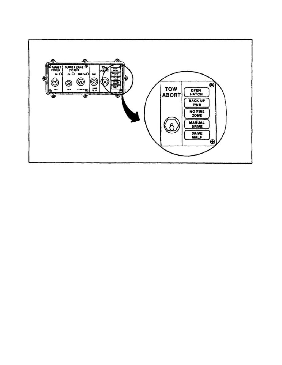
FIGURE 30.
THE TURRET CONTROL BOX.
(4) Next, PFC Elrond turns the ENGINE ACCESSORY switch ON and
notes that the ENGINE ACCESSORY indicator light does come ON.
(5) So far, everything is working as it should, so PFC Elrond
starts the engine.
The engine is supposed to start in less than
three tries and it starts on the second try. Therefore, PFC Elrond
checks the VOLTS gage on the driver's instrument panel.
The VOLTS
gage is reading about in the middle of the green zone--as it should
be--with the engine running. Therefore, PFC Elrond stops the engine.
He now knows that no faults are present in the fire suppression
system.
d. Pathway Two.
To arrive at troubleshooting pathway two, the
initial tests were performed with the following results: test number
67 indicated the presence of more than 20 volts; the gage pressure
readings on both squad area fire bottles were within the normal
ranges; the STE-M1/FVS was removed from the vehicle; the fire
suppression system was deactivated; the vehicle ground cable was
installed; and the MANUAL light did NOT come ON.
Again, since
exploring all of the possible test results for the actual procedure
can become quite lengthy and complicated, let's observe PFC Elrond
performing the task to see some of the test results that might be
obtained while troubleshooting.
45


 Previous Page
