M2/M3 BFV: FIRE SUPPRESSION SYST - OD1607 - LESSON 2/TASK 2
disconnects the STE-M1/FVS from the
vehicle
and
begins
the
troubleshooting procedure described next.
NOTE
The procedure described below is being used as an
example.
The test results described in this
pathway are not the only results possible when
performing
the
troubleshooting
procedures.
Always follow the directions in the TM for the
actual test results obtained when troubleshooting
on the vehicle.
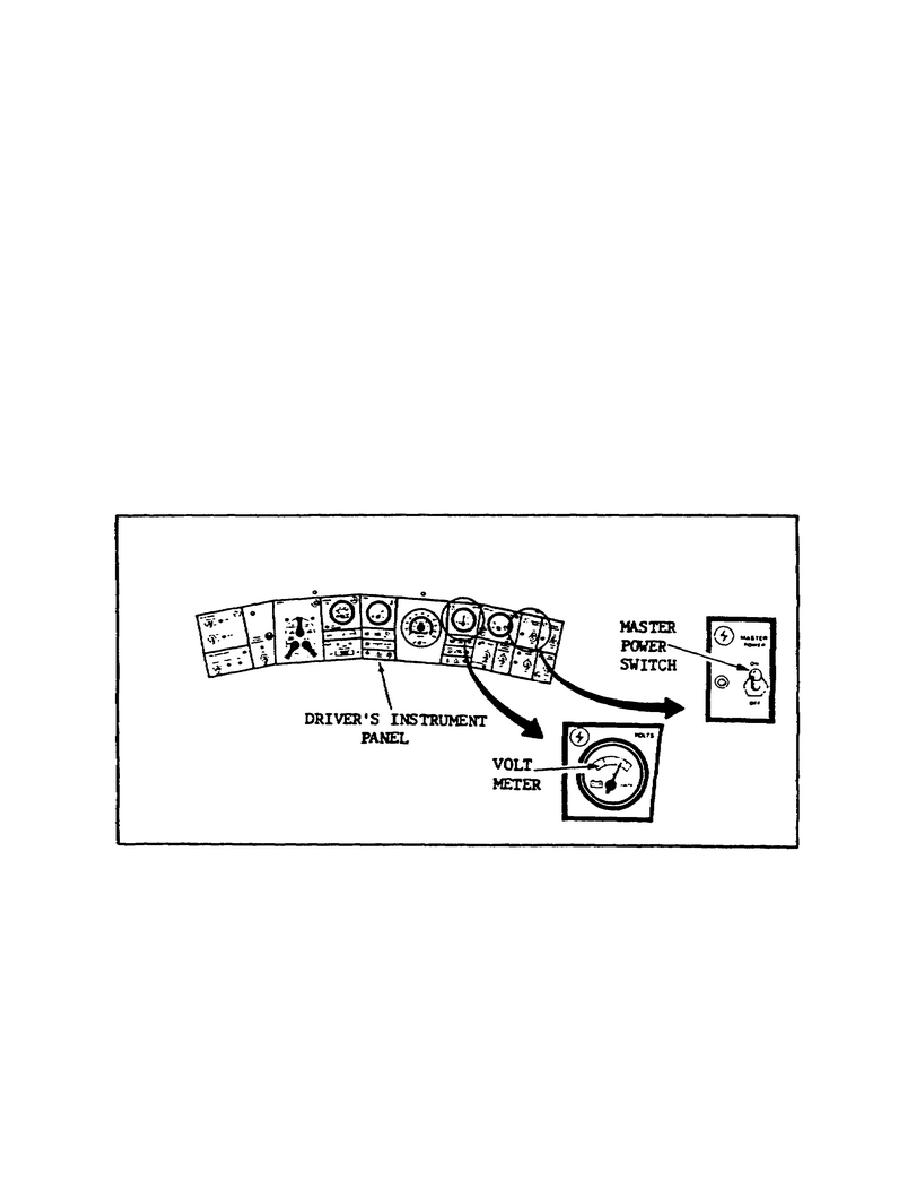
(1) PFC Elrond turns ON the MASTER POWER switch on the driver's
instrument panel (figure 29).
He knows that the VOLTS gage on the
driver's instrument panel should read somewhere from in the lower
half of the yellow zone to the green zone.
FIGURE 29.
THE DRIVER'S INSTRUMENT PANEL.
(2) Since PFC Elrond notes that the gage reads in the lower
half of the yellow zone, he checks and finds that the MASTER POWER
indicator light is ON, as it should be.
(3) PFC Elrond turns ON the TURRET POWER switch on the turret
control box (figure 30 on the following page).
Since the BACKUP
POWER annunciator light does NOT come ON, he turns the TURRET POWER
switch OFF.
44


 Previous Page
