M2/M3 BFV: FIRE SUPPRESSION SYST - OD1607 - LESSON 2/TASK 2
When following the troubleshooting pathways in this subcourse, it is
important to remember that the test results described are not the
only possible results. The pathways are being used as examples only.
It is essential to have the TM present and to respond to the specific
test results obtained according to the directions in the TM if actual
troubleshooting procedures are to be performed on the vehicle. Also,
this subcourse assumes that whenever a test is performed, the test
equipment or multimeter has been properly set up for the test being
described.
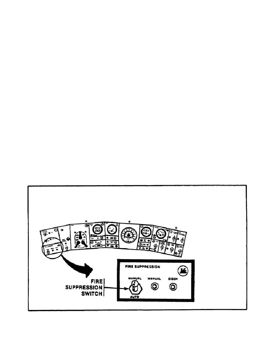
a. Preparing to Troubleshoot. Before beginning a troubleshooting
task, it is important to have on hand the tools and parts required,
and make sure the vehicle is properly set up for the task at hand.
For this troubleshooting task, the vehicle engine should be stopped
and the FIRE SUPPRESSION switch should be in the MANUAL position
(figure 26).
The general mechanic's tool kit (automotive), a
multimeter, electrical connector pliers, the fire suppression system
test equipment, a probe assembly, a cotter pin, and the STE-M1/FVS
(vehicle test meter (VTM) only) test set will be needed to perform
this task.
When actually performing the step-by-step procedures on
the vehicle, a helper may be needed, depending on the test results
obtained.
FIGURE 26.
FIRE SUPPRESSION SWITCH.
39


 Previous Page
