M2/M3 BFV: HULL POWER DIST SYSTEM - OD1606 - LESSON 1/TASK 1
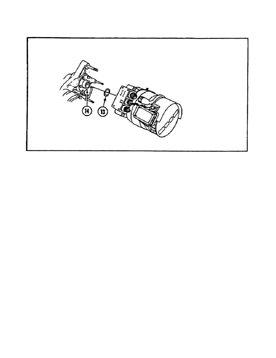
FIGURE 13.
REMOVING THE PREFORMED PACKING.
Next, mount the generator on the studs and slide it forward while
guiding the splined shaft into the PTO.
This particular step
requires an assistant. Once the generator is mounted onto the studs,
install four new lockwashers and nuts on the studs.
Now install the ground lead 3W5E2 and electrical lead 3W4E2 on
terminal 3A2G1E1 of the generator. Then install a new lockwasher and
nut on the terminal. Next, install plug 3W4P1 on jack 3A2G1J1. Be
sure to use electrical connector pliers when connecting the plug.
Install the vehicle ground cable following the procedures outlined in
paragraph 4a on page 10 of this task. Once the vehicle ground cable
has been installed, unstow squad seat number 4 (if installed).
Adjust the generator output voltage by unscrewing coupling (3)
(figure 14 on the following page) and remove the plug (1) from the
generator (2). Use electrical connector pliers.
Reinstall the plug and align the mark (4) with the voltage position
shown on the instruction plate (5).
Hold the mark in the aligned
position and install the plug on the generator. Tighten the coupling
using electrical connector pliers.
15


 Previous Page
