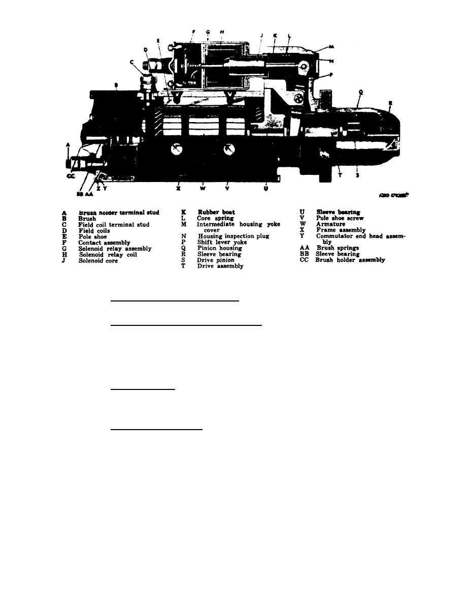
Figure 8.
Starter assembly.
(3) Commutator end head assembly. The commutator end head assembly (Z)
serves as an end closure for the frame and a bearing support for the armature.
(4) Brushes and brush holder assembly. The eight brushes (B), which
function as the electrical contact to the commutator, are supported by four brush
holders in the holder plate. They are held in contact with the commutator by eight
helical torsion brush springs (AA). Two of the brush holders are connected to the
brush holder terminal stud (A). This extends through the commutator end head. The
remaining brush holders are connected to a field coil. The brush holder assembly
is attached to the frame assembly with three screws.
(5) Pinion housing. The pinion housing (Q) serves as a bearing support
for the drive end of the armature shaft. It is also a housing for the drive pinion
(S). The starter is mounted to the engine with this housing. Three holes are
provided for attachment to the engine.
(6) Intermediate housing. The intermediate housing (M) consists of two
parts bolted together. The lower part serves as the armature center bearing
support and end plate for the starter motor. The upper part houses the drive
assembly (T) and shift lever yoke (P).
OS 010, 6-P9


 Previous Page
