

Figure 1-46.
Reverse Shift Valve.
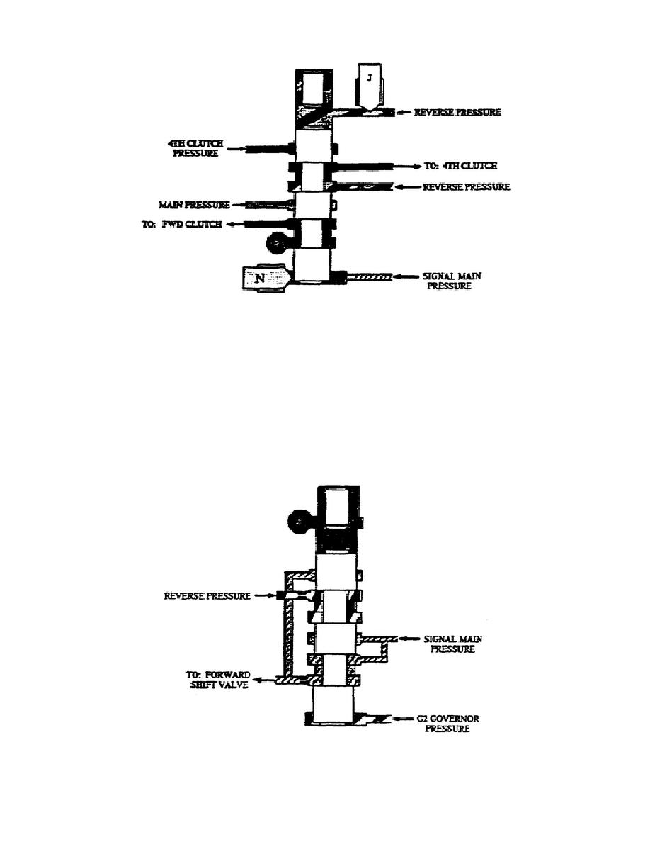
af. Forward and Reverse Inhibitor (fig. 1-47).
This valve
assembly consists of a valve, stop, and a calibrated spring in a
bore.
Directing G2 governor pressure to the forward and reverse inhibitor
moves it up against its stops.
The valve body blocks signal main
pressure and allows reverse pressure to flow through.
Releasing G2
governor pressure from the bottom allows the spring to force the
valve back down, enabling signal main pressure through and blocking
reverse pressure.
Figure 1-47.
Forward and Reverse Inhibitor.
47
OD1710


 Previous Page
