

Figure 1-50.
Priority Valve Hydraulic Circuit.
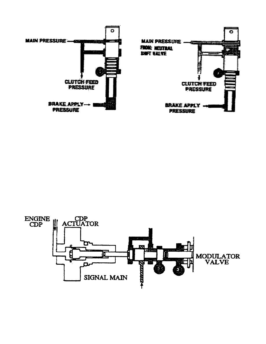
d. Modulator Pressure Circuit (fig. 1-51).
The modulator valve
produces a regulated, reduced pressure from the signal main pressure.
When the engine throttle closes, a spring moves the valve to the
left.
When the engine throttle opens, the compressor discharge
pressure actuator moves the valve to the right. When spring force at
the right is in balance with the CDP at the left, modulator pressure
is regulated.
Increasing the throttle setting causes the CPD to move, forcing the
modulator valve to the right, and reducing the modulator pressure.
Decreasing the throttle setting decreases the force on the CDP
actuator and allows the spring force to return the valve to the left,
increasing the modulator pressure.
Modulator pressure varies with
the throttle opening and closing.
Figure 1-51.
Modulator Pressure Circuit.
50
OD1710


 Previous Page
