

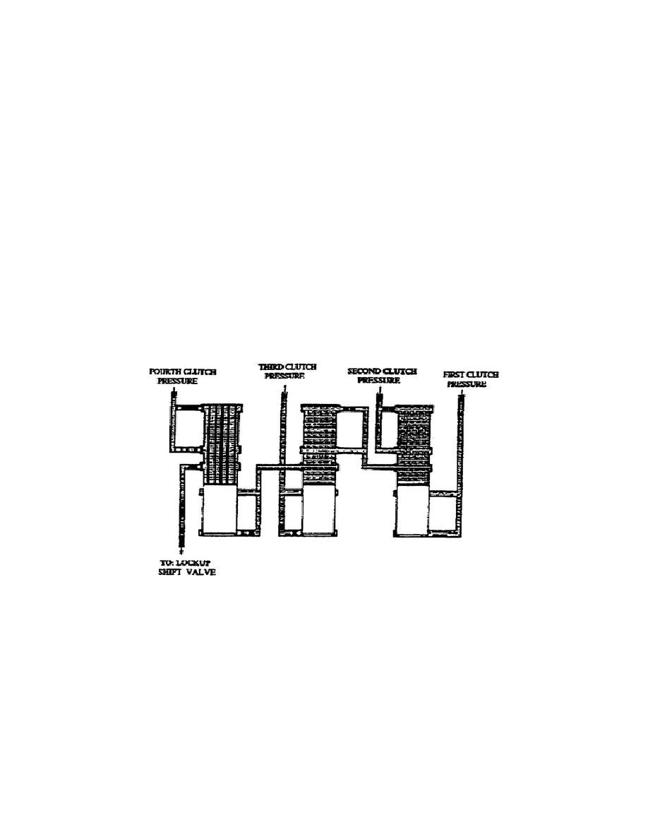
h. Lockup Clutch Cutoff Circuit (fig. 1-55). Applying either the
first, second, third, or fourth clutch sends pressure to the lockup
cutoff valves. In the first range, this pressure pushes the valve up
and allows pressure to charge the lockup feed line. Lockup occurs in
the first range when the turbine speed governor (G1) is high enough.
When the transmission shifts to the second range, first clutch
pressure exhausts to the reservoir and releases the lockup clutch.
Second clutch apply pressure pushes (through an orifice) on the
opposite end of the 1-1 cutoff valve to reapply the lockup clutch.
However, oil initially flowing through the orifice in the 1-2 cutoff
valve delays application of the lockup clutch.
The release of the lockup and delay in reapplication of the lockup
allows smoother shifts.
Similar actions of the lockup clutch cutoff valves occur at the 2-3
and 3-4 cutoff valves when releasing the second and third clutches.
In downshifts, similar operations occur, but in a reverse order.
Figure 1-55.
Lockup Clutch Cutoff Circuit.
i. Service Brake Circuit.
Several valves in the service brake
circuit function during braking operation to influence pressures,
flow, etc.
The following paragraphs discuss each valve as it
functions in forward and reverse operations, brakes released (OFF)
and brakes applied (ON).
54
OD1710


 Previous Page
