

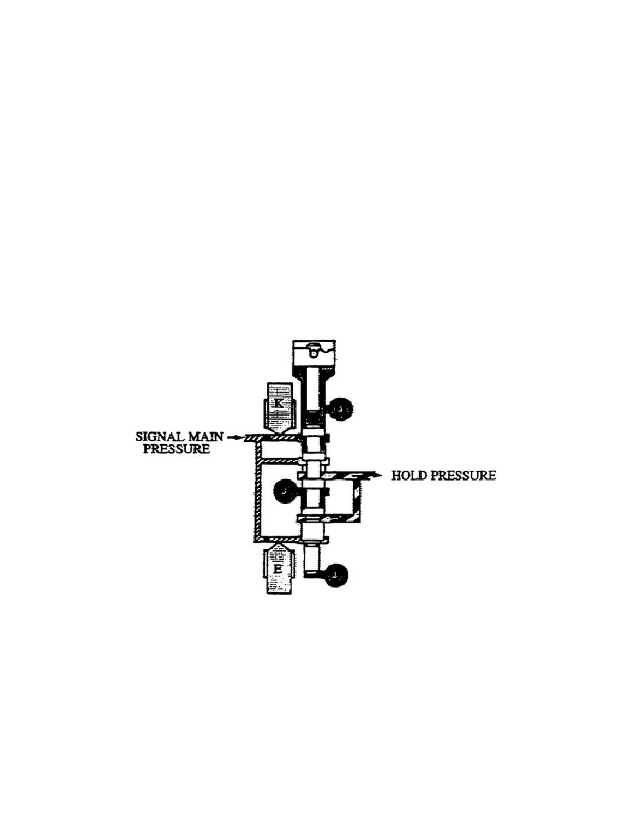
z. Hold Regulator (fig. 1-41). This regulating valve consists of
a valve, valve plug, calibrated spring, plain washer, adjusting ring,
and a pin in a bore.
Energizing solenoid E allows spring force to move the valve
down
partially.
This movement allows a partial flow of signal
main
pressure through the valve.
Energizing solenoids E and K
allow
spring force to move the valve down completely for maximum
flow
through the valve.
Solenoid E controls the movement up of the valve. When solenoid E is
not energized, hydraulic pressure overcomes spring force and moves
the valve up, preventing signal main pressure from flowing through
the valve.
The forward and reverse valve body, located on the left side of the
main valve body, contains six valves in their respective bores:
lockup cutoff valve, lockup shift valve, neutral shift valve, forward
shift valve, reverse shift valve, and inhibitor valve.
Figure 1-41.
Hold Regulator Valve.
aa. Lockup cutoff valve (fig. 1-42). This valve assembly includes
a valve, stop, and calibrated spring in a bore.
Spring force pushes the valve up and allows lockup pressure to flow
through the valve. When directing brake apply pressure to the top of
the valve, hydraulic pressure overcomes spring pressure and pushes
the valve down, stopping the pressure flow.
43
OD1710


 Previous Page
