

Figure 1-42.
Lockup Cutoff Valve.
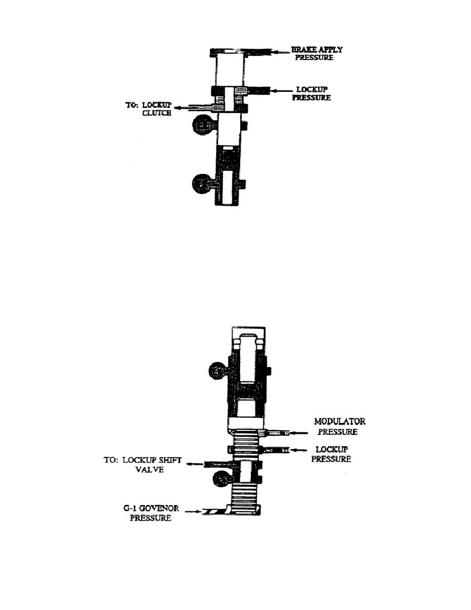
ab. Lockup Shift Valve (fig. 1-43).
The lockup
shift
valve
assembly includes a valve, stop, and calibrated spring.
Spring force pushes the valve down and prevents lockup pressure from
flowing through the valve. Applying G2 pressure to the bottom of the
valve moves it up against the stop, allowing lockup pressure through.
Directing modulation pressure to the valve allows the valve to move
up with less pressure from the bottom.
Figure 1-43.
Lockup Shift Valve.
44
OD1710


 Previous Page
