

Figure 1-39.
Trimmer Valve.
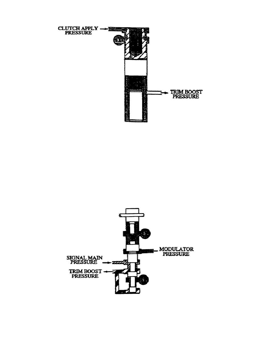
y. Trimmer Boost Valve Body (fig. 1-40). This valve is located
on top of the main control valve body. The trimmer boost valve body
contains the trim boost regulator.
Spring force pushes the valve down and allows signal main pressure to
flow through the valve. Oil pressure directed to the bottom of the
valve regulates the flow of oil through the valve.
Directing
modulator pressure to the upper land area of the valve moves it up
and decreases the oil flow through the valve. The upward movement of
the valve is proportional to the amount of modulator pressure
present.
Figure 1-40.
Trim Boost Regulator.
42
OD1710


 Previous Page
