MAINTENANCE OF M939 SERIES VEHICLES - OD1661 - LESSON 1/TASK 2
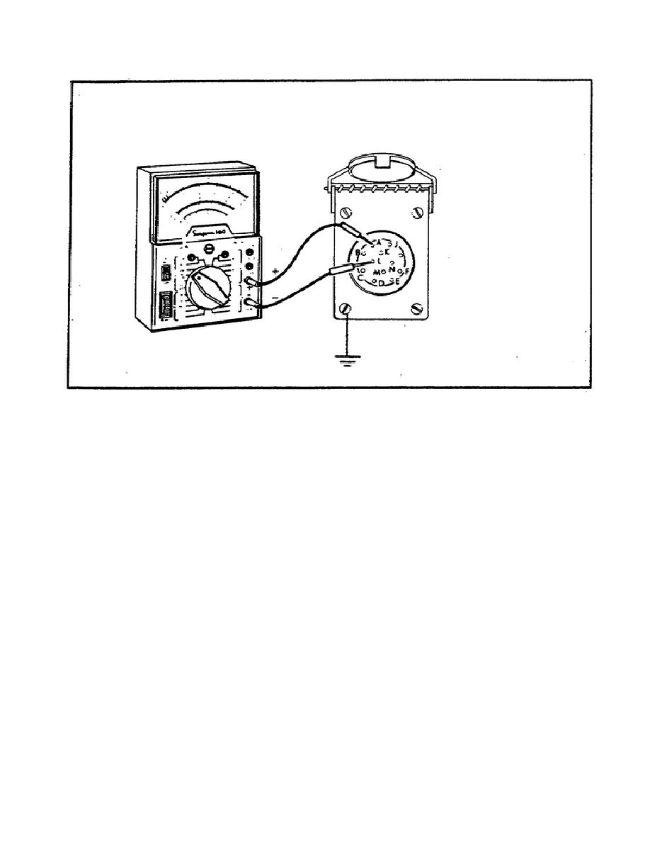
FIGURE 27.
TESTING TRAILER RECEPTACLE
VOLTAGE.
(2) Troubleshooting Procedure for the Malfunction ONE OR MORE
TRAILER LIGHTS INOPERATIVE, Step 2. In this step, SGT Markum will be
testing the trailer receptacle ground. To do this, SGT Markum first
sets the multimeter to RX1 for continuity reading.
He now connects
the positive meter lead to the circuit 90 wire at the socket
(receptacle terminal L and then D).
He then connects the negative
meter lead to the chassis. The meter should indicate continuity from
both L and D to the chassis. Since continuity was not present, SGT
Markum will repair circuit 90 wire and then continue troubleshooting
the malfunction ONE OR MORE LIGHTING SYSTEMS DO NOT FUNCTION ON THE
TRAILER.
Step 2.
SGT Markum tests the trailer connecting cable for
continuity.
He begins this procedure by first removing the
connecting cable from the truck.
He then places both ends of the
cable at a convenient point near each other, opens and locks open the
hinged covers on each end of the cable.
With the multimeter still
set to RX1 for reading continuity, SGT Markum now connects the meter
leads from socket A on one connector to socket letter A on the other
connector as shown in figure 28 (on the following page).
61


 Previous Page
