MAINTENANCE OF M939 SERIES VEHICLES - OD1661 - LESSON 1/TASK 2
First, SGT Pearlswieg ensures that the battery switch is in the OFF
position.
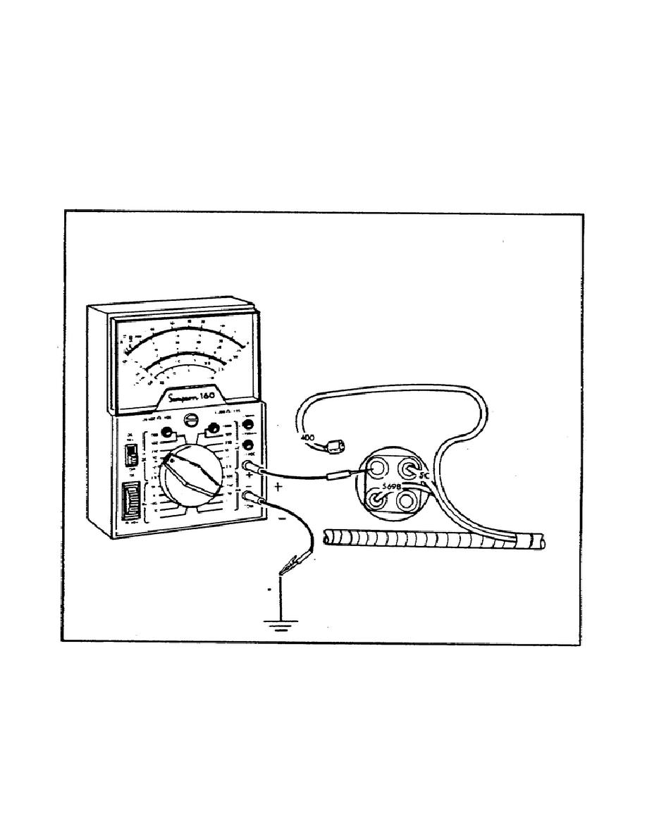
He then disconnects the circuit 400 wire for the heater
switch. With the wire disconnected, he places the battery switch to
the ON position. SGT Pearlswieg sets the multimeter to the 50 volt
range, and connects the negative meter lead to the vehicle chassis
for ground. He then touches the positive meter lead to the circuit
400 wire terminal on the switch and notes the reading, as shown in
figure 29.
FIGURE 29.
TESTING THE HEATER CIRCUIT
(CIRCUIT 400 WIRE).
With the switch in the LOW position, the meter should indicate 12 or
13 volts and battery voltage when the switch is in the HIGH position.
The correct voltages were found, and the heater still does not
operate; this indicates that the heater itself is defective and
should be replaced.
The procedures for replacing the heater can be
found in paragraph 9-35 of TM 9-2320-272-20-2.
63


 Previous Page
