2.
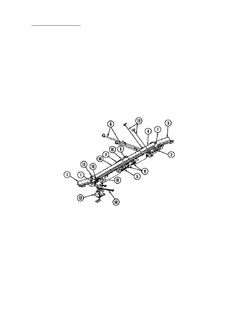
The Conveyor Assembly.
The conveyor is a hydraulically powered assembly that can be operated in either the
forward or reverse directions. Two stationary dead end sections, one at each end,
are used as staging areas for ammunition transfer.
The powered parts of the
conveyor are the drive end, center, and take-up end sections.
A three position
switch located on the hydraulic control panel actuates the solenoids attached to
the conveyor directional control valve. This allows the conveyor motor to operate
in either forward or reverse. An override safety (ON/OFF) switch, located at the
take-up end section, provides a shut-off capability outside of the vehicle.
A
drive sprocket coupled to the motor shaft moves the conveyor chain.
The chain runs taut across the top of the conveyor and loose across the bottom. A
chain adjustment device allows chain tension to be adjusted by moving the idler
sprocket forward or backward.
Telescoping support arms serve to adjust and lock
the conveyor in several operating positions.
Two cable assemblies support the
conveyor while it is being deployed.
They are removed and stowed when it is in
operation. A handcrank, for manual operation, is provided in case of a hydraulic
system malfunction. The conveyor can be folded and stowed inside the vehicle when
not in use (Fig. 1).
Figure 1.
Conveyor Assembly.
You have completed the introduction to the M992 Ammunition Carrier and the
description of the conveyor assembly. The next part of this lesson describes the
maintenance procedures for the components of the conveyor assembly.
3
OD1737


 Previous Page
