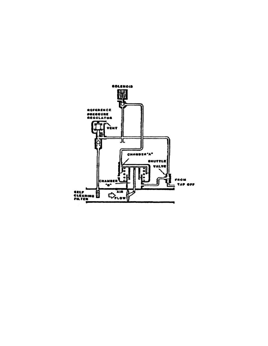
Since chamber A has a larger surface area than chamber B, chamber A
overpowers chamber B, the actuator moves, and the linkage opens the
valve.
When the downstream sensing port has greater pressure than the
pressure from the reference pressure regulator, the shuttle valve
moves and allows the pressure from the downstream sensing port to
enter chamber B.
When enough pressure has entered chamber B to
overcome the pressure in chamber A, the valve moves toward the closed
position.
Figure 1-14.
Pressure Regulating Valve Schematic.
If the cutoff solenoid fails to energize,
the valve opens when applying air pressure.
5.
Flow Limiting Venturi (fig. 1-15}.
The venturi mounts on the outlet of the pressure regulating valve
using a V-band type clamp.
The pressure sensing lines from the
pressure regulating valves also mount on the venturi (fig. 1-16).
Operation.
The venturi serves as an in-line restrictor
with a 0.570 inch diameter, with one inlet and three
outlets, and a manifold block for air pressure tapoffs
(fig. 1-17). The venturi is designed to limit air flow to
approximately 200 cfm when 35 psig is available.
The
outlets of the venturi are for airflow to the heat
15
OD1705


 Previous Page
