Home
Download PDF
Order CD-ROM
Order in Print
Home
>
Ordnance Documents and other related manuals
>
> Figure 1-13. Pressure Regulating Valve Location
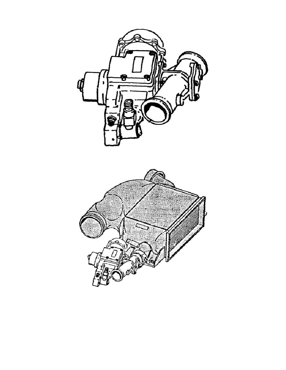
Pressure Regulating Valve (fig. 1-12).
Figure 1-14. Pressure Regulating Valve Schematic
NBC Protection System M1A1 Series Tank
Page Navigation
9
10
11
12
13
14
15
16
17
18
19
Figure 1-12.
Pressure Regulating Valve
.
Figure 1-13.
Pressure Regulating Valve
Location.
The pressure then goes to chamber A, the opening chamber of the
actuator.
Chamber
A has a greater surface area than chamber B, which
is receiving the
same
pressure.
14
OD1705