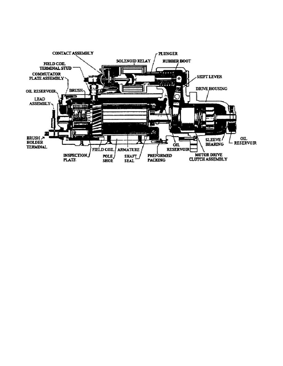
o Shift lever housing.
o Solenoid plunger.
Figure 16.
Starter Motor.
u. The Blower Assembly (Fig. 17).
The blower assembly bolts on
the cylinder block and supplies fresh air for the engine to use
during scavenging, intake, and compression.
Basically it is an air
pump; two hollow double lobe rotors revolve in a housing, providing a
continuous and uniform flow of air into the engine air box.
This engine uses a bypass blower and bypass relief valve. The spring
loaded bypass valve is at the rear of the blower end plate.
The
valve is closed at engine start-up, during low rpm, and during light
load conditions. As engine speed and rpm increase, the turbocharger
speed increases causing an increase in the air box pressure for
scavenging the engine cylinders.
At 10" Hg air box pressure, the
bypass valve begins to open; it is fully open at 13" Hg.
With the
valve in the open position, this allows incoming air to flow through
the blower lobes and end plate to the airbox. The blower continues
to operate with the valve open, but requires less engine power
because the pressure rise across the blower is greatly reduced,
resulting in increased fuel economy.
Viewed externally, the bypass valve is a small hose and tube through
the blower end plate.
A very small amount of air bleeds past the
valve and passes through the hose to help keep the
21
OD1713


 Previous Page
