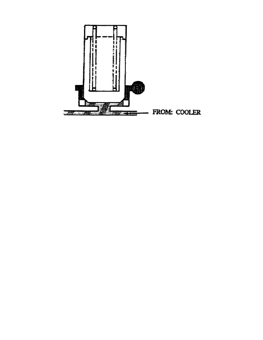
Figure 1-28.
Lube Regulator (Cooler Dump Valve).
n. Brake Apply Regulator (fig. 1-29). The brake apply regulator
valve consists of two valves, three calibrated springs, and a rod and
nut in a bore.
When the brake apply lever exerts pressure on the brake apply
regulator valve, mechanical force overcomes the spring force and the
valve moves to the left. This allows main pressure to flow through
the right land areas of the valve and then to the left land areas.
NOTE:
The amount of pressure flowing through the brake regulator
valve is proportional to the movement of the brake apply
lever.
When the brake apply lever is not exerting pressure on the right side
of the valve, spring force moves the valve to the right and prevents
main pressure from flowing between the left land areas of the
regulator valve.
This still allows pressure (when present) to flow
between the right land areas.
o. Primary Brake Coolant Valve (fig. 1-30).
The primary brake
coolant valve consists of a valve, calibrated spring, seal, guide
pin, and cover.
Spring force moves the valve to the right.
The valve then directs
cooler-out pressure through the left portion of the valve only.
Applying brake signal pressure to the right end of the valve allows
hydraulic pressure to overcome the spring force, moves the valve to
the left, and allows cooler-out oil to flow through the right portion
of the valve.
34
OD1710


 Previous Page
