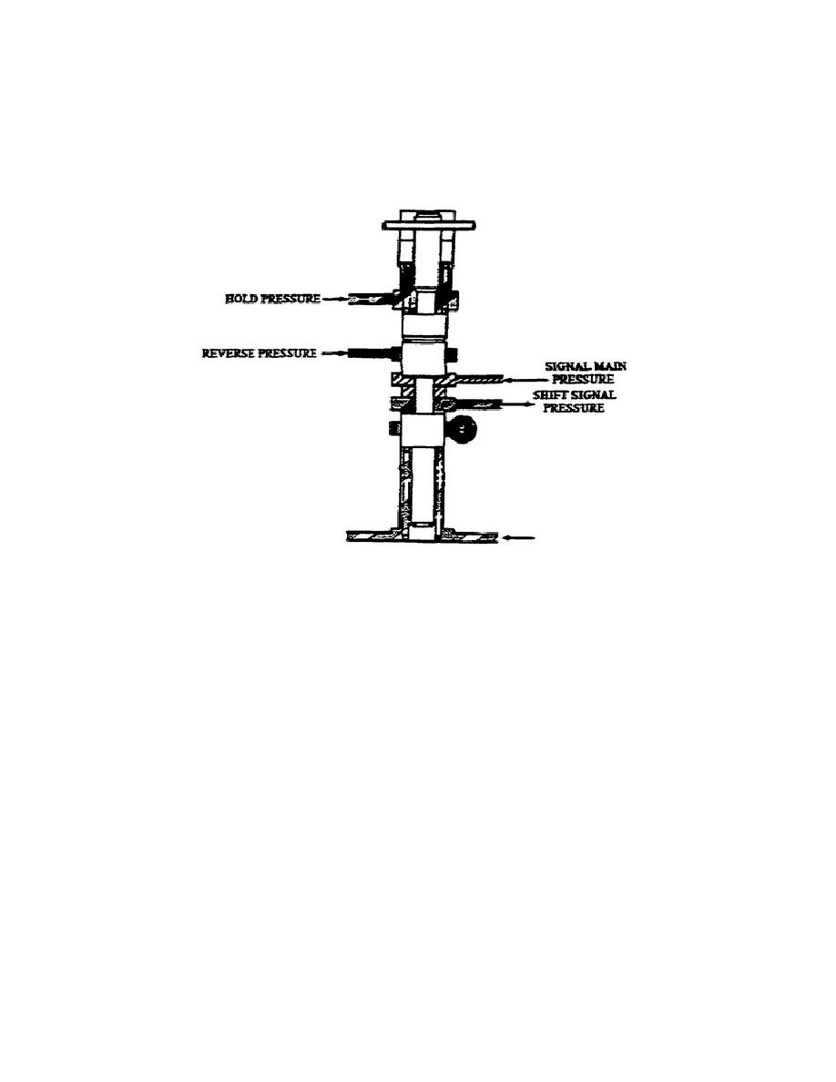
Without hold pressure at the top of the valve, the lower spring force
pushes both valves up against the stop and allows signal pressure to
flow through the middle lands of the valve.
By directing hold
pressure to the top of the valve, hold pressure and the upper spring
force move the valve down. This blocks signal main pressure flow and
returns signal pressure to the reservoir.
Figure 1-35.
1-2 Signal Valve.
u. 2-3 and 3-4 Signal Valves (fig. 1-36).
Each signal valve
consists of a signal valve and modulator valve, calibrated spring,
stop, and an adjusting ring in a bore.
Although the 2-3 and 3-4
signal valves are not identical, their operation is the same.
Applying G2 governor pressure to the bottom of the signal valve moves
the valve against the stop and permits signal main pressure to flow
through the valve. Spring force moves the valves away from the stop
when G2 pressure drops low enough.
Two other pressures can change
the movement schedule of the shift signal valves:
(1) When hold pressure between the modulator and signal valves
is present, a higher pressure at the bottom of the signal valve is
needed to move it up.
(2) Directing modulator pressure to the modulator valve lowers
the pressure needed to move the signal valve up.
39
OD1710


 Previous Page
