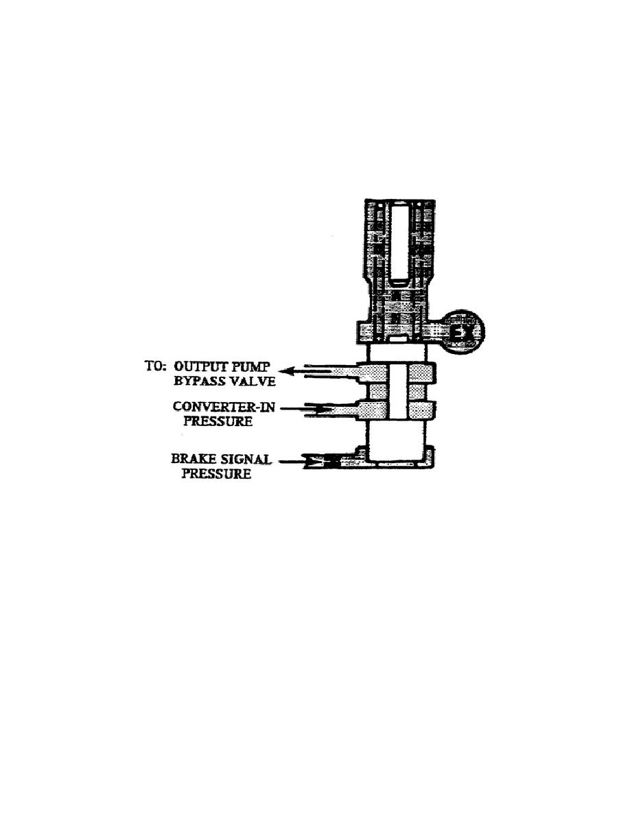
s. Out Pump Signal Valve (fig. 1-34).
The output signal valve
assembly consists of a valve, calibrated spring, and a stop in a
bore.
Spring pressure pushes the valve down and enables converter-in
pressure to flow between the land areas of the valve. Applying brake
apply pressure overcomes spring force and moves the valve up.
This
prevents the converter-in pressure from flowing between the lands and
directs the oil back to the reservoir.
Figure 1-34.
Output Pump Signal Valve.
The main control valve body, located at the rear of the transmission
center section, consists of the following valves:
clutch trimmers,
lockup clutch cutoff valves, 1-2, 2-3, 3-4 signal valves, 1-2, 2-3,
3-4 shift valves, hold regulator valve, and the priority valve.
t. 1-2 Signal Valve (fig. 1-35). This valve consists of a signal
valve, two calibrated springs, stop, plug, and a pin in a bore.
38
OD1710


 Previous Page
