

Figure 1-32.
Electric Brake Lube Valve.
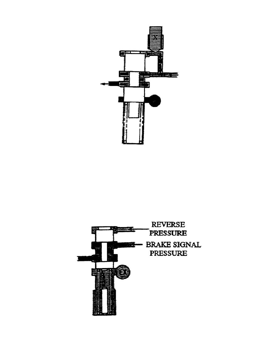
r. Reverse Signal Brake (fig. 1-33).
This valve consists of a
valve and calibrated stop in a bore.
Spring pressure pushes the valve up allowing brake signal pressure
through the land areas of the valve.
Applying reverse pressure to
the top of the valve allows hydraulic pressure to overcome spring
force and move the valve.
This prevents brake signal pressure from
flowing between the land areas and allows pressure to be relieved to
the reservoir.
Figure 1-33.
Reverse Signal Brake Valve.
37
OD1710


 Previous Page
