

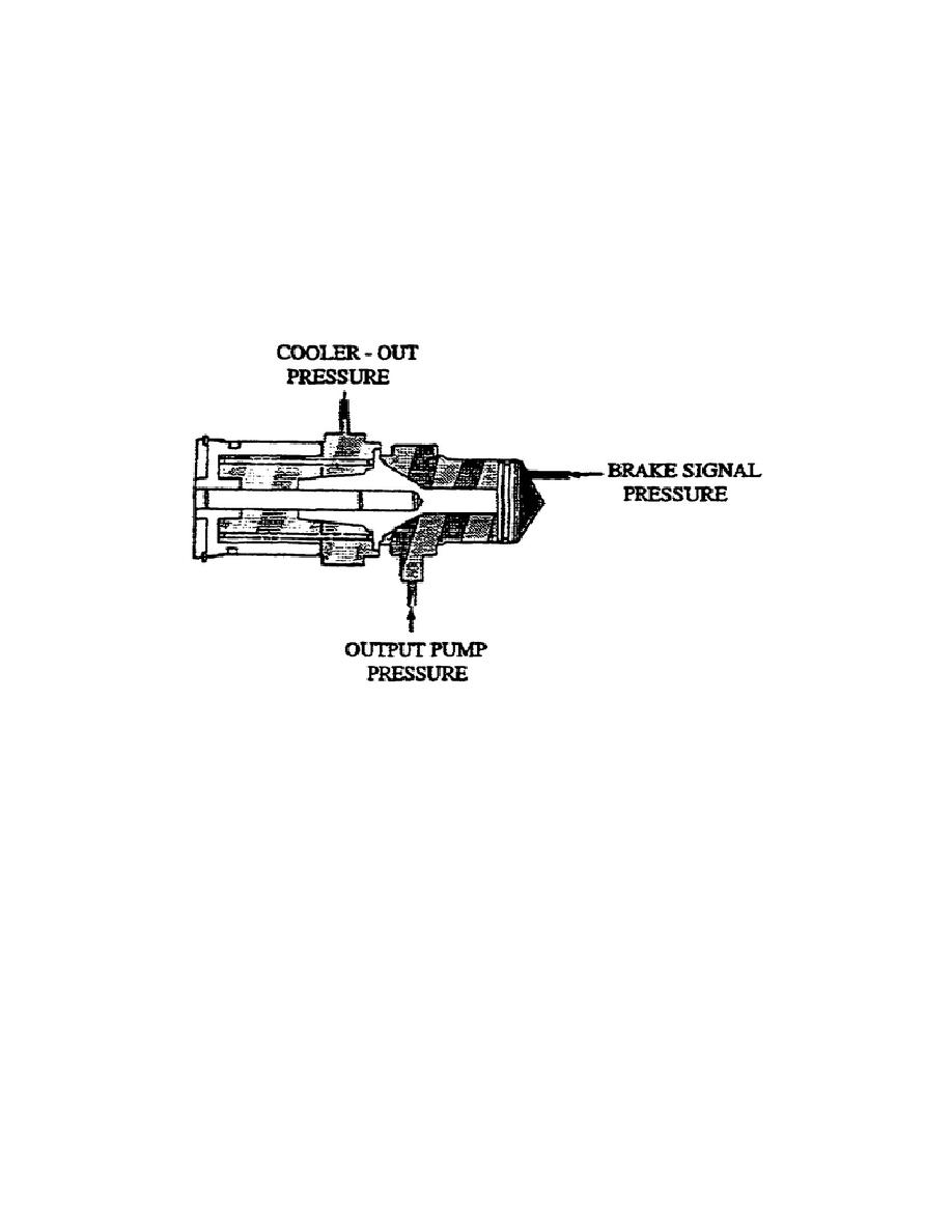
p. Secondary Brake Coolant Valve (fig. 1-31).
This assembly
consists of a valve, calibrated spring, seal, guide pin, and cover.
When no brake signal pressure is applied to the right end of the
valve, spring force moves the valve to the right and prevents oil
from flowing through the valve.
When applying brake signal pressure to the right end of the valve,
hydraulic pressure overcomes the spring force. This moves the valve
to the left and allows output pump discharge pressure to flow through
the valve.
Figure 1-31.
Secondary Brake Coolant Valve.
q. Electric Brake Lube Valve (fig. 1-32).
The electric brake
lube valve consists of a valve and a calibrated spring in a bore.
Solenoid X, which is not energized during normal operations, controls
the movement of the electric brake valve. This allows main pressure
to push the valve down against the spring force, preventing main
pressure from flowing through the valve. When solenoid X energizes,
main pressure returns to the reservoir from the top of the valve.
This allows spring force to push the valve up and main pressure to
flow through the valve.
The output pump valve body assembly, located on the bevel gear
carrier assembly, contains the reverse signal brake valve and output
pump signal valve.
36
OD1710


 Previous Page
