

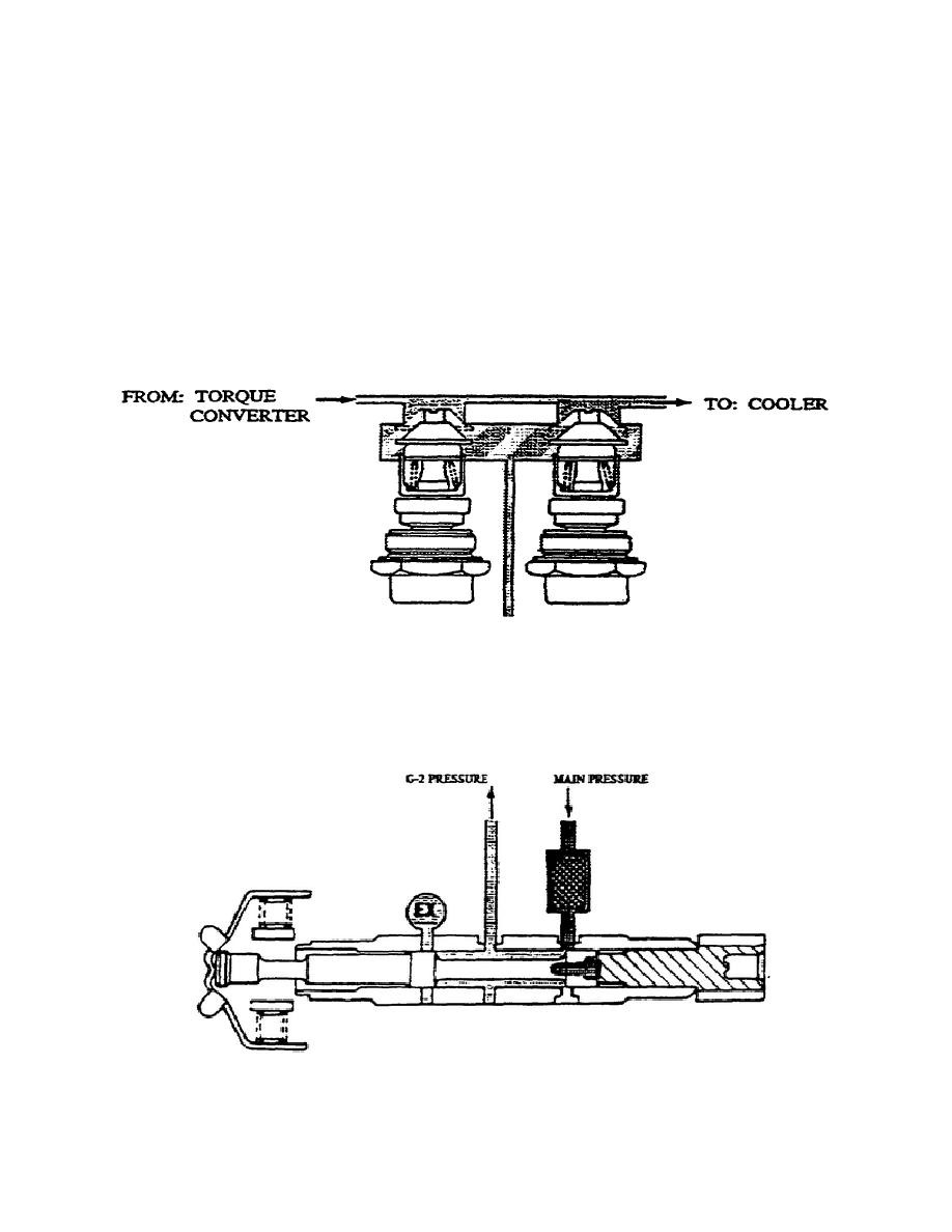
j. Cooler Bypass Valves (fig. 1-25).
The two cooler bypass
valves are pressure and thermo regulating valve assemblies located in
the input module.
When hydraulic pressure (directed to the cooler) exceeds the
calibrated spring force in the valve assembly, the valve opens and
allows oil to bypass the cooler. When the oil reaches approximately
150ƒF, the valve closes and directs the oil to the cooler.
k. Output Speed Governor G2 (fig. 1-26).
The output speed
governor assembly is a centrifugal (flyweight) governor driven by a
gear integral with the rear carrier output shaft. A bore and cover
in the right output support this valve.
Figure 1-25.
Cooler Bypass Valve.
Rotation of the governor causes the governor valve to travel within
its bore. When the valve moves right, governor pressure rises. When
the valve moves left, governor pressure falls. Governor pressure is
proportional to range output speed.
Figure 1-26.
Output Speed Governor.
32
OD1710


 Previous Page
