TROUBLESHOOTING THE M998 ELECT SYST. - OD1617 - LESSON 1/TASK 1
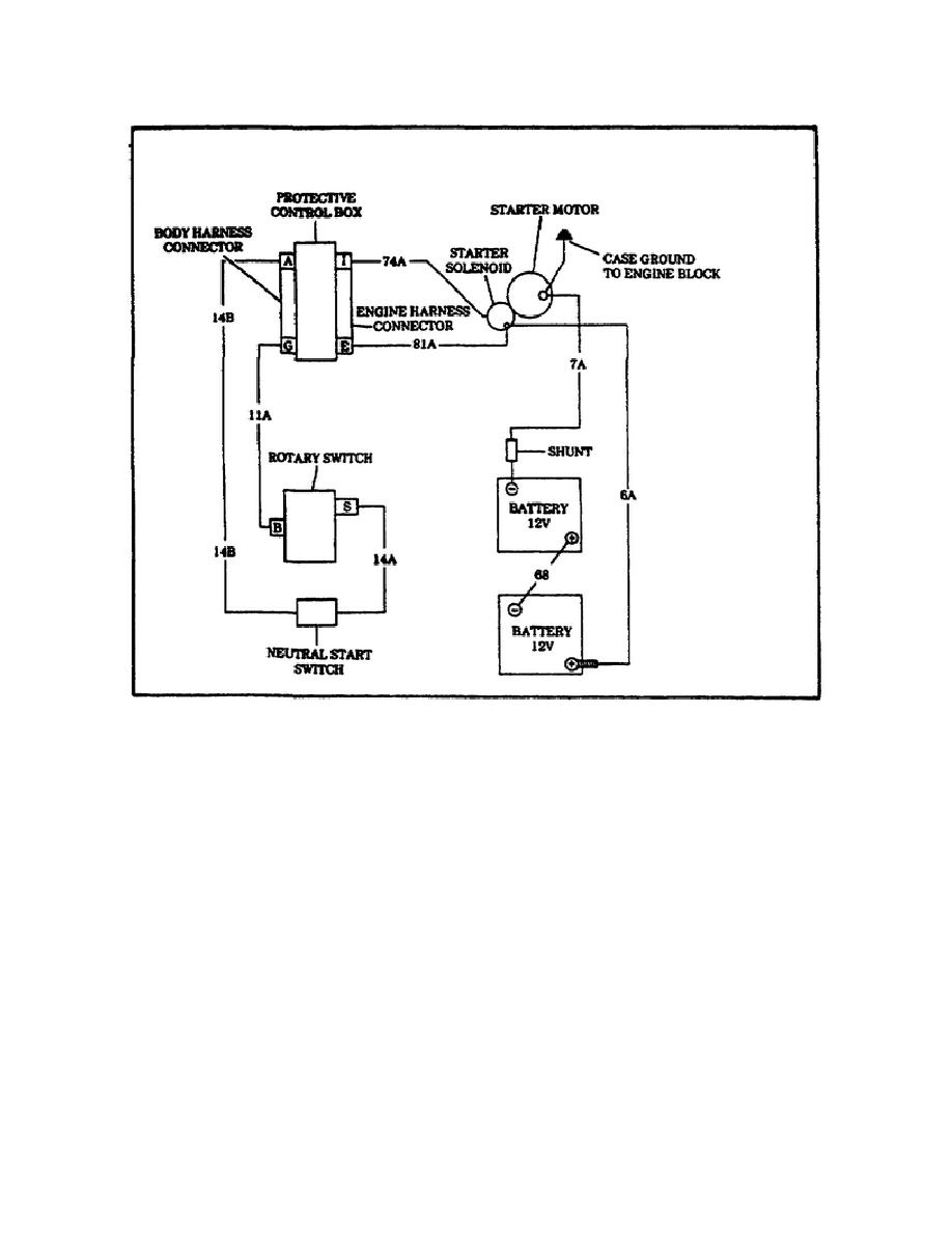
FIGURE 3.
STARTING SYSTEM SCHEMATIC.
Step 3. Disconnect lead 14B from the neutral start switch and check
for battery voltage at the neutral start switch lead 14 with the
rotary switch in the START position. If battery voltage is present,
disconnect the negative battery cable from the battery, both cannon
plugs from the protective control box and lead 74A from the starter.
Ground lead 74A and check pin I on the engine wiring harness cannon
plug for the control box. If continuity is present, check lead 14B
on the neutral start switch to pin A on the body wiring harness
cannon plug for the control box.
If continuity is present, replace
the protective control box, following the procedures in paragraph 4-5
of the TM. If continuity is not present, repair the wiring harness,
following the procedures in paragraph 4-62 of the TM. If the wiring
harness is beyond repair, notify IDS maintenance.
Reconnect the
protective control box cannon plugs, neutral start switch lead 14B,
starter lead 74A to the starter, and the negative battery cable to
the battery.
15


 Previous Page
