OD1402 - Lesson 1/Learning Event 1
NOTE
The signal can also be changed with the red vernier on
the VOLTS/DIV knob. However, when this control is used
the vertical amplitude is no longer calibrated. Always
leave this vernier fully clockwise to CAL when measuring
amplitude.
Step 7. Disconnect the cable between the INPUT of the vertical
amplifier and the CALIBRATOR connector. Connect a probe or a
signal input cable to the INPUT connector of the left vertical
amplifier.
The Graticule
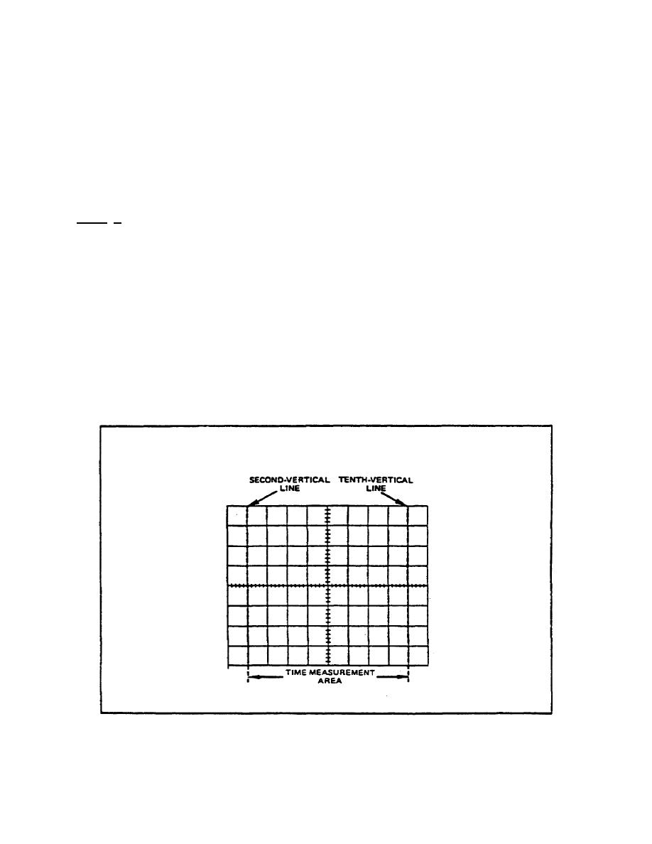
Before we can start determining voltage amplitudes and frequencies,
we must know a little about the screen grids (graticule). The
graticule is marked on the inside of the CRT faceplate, providing
for distortionfree measurements. The graticule (figure 10, below)
is arranged in 8 vertical and 10 horizontal divisions, with each
division 1 centimeter square. Thus, with calibrated vertical and
horizontal circuits, accurate measurements can be made.
FIGURE 10. GRATICULE MEASUREMENT LINES.
21


 Previous Page
