OD1402 - Lesson 1/Learning Event 1
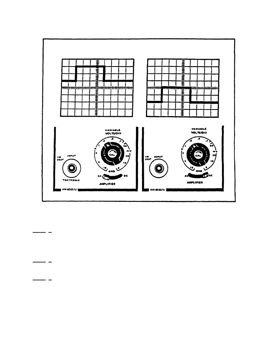
FIGURE 12. MEASURING DC LEVEL.
Horizontal Calibration
Step 1. Connect a cable between the CALIBRATOR connector and the
INPUT connector of the left vertical amplifier. The output
frequency of the CALIBRATOR is 1000 Hertz, with a voltage of 1 volt
peaktopeak.
Step 2. Turn the TIME/DIV OR DLY TIME switch to the .1ms position.
One cycle should be displayed on the CRT.
Step 3. With a small screwdriver, rotate the SWP CAL control until
the displayed waveform of one cycle covers exactly 10 divisions
horizontally (figure 13, on the next page).
24


 Previous Page
