9.
LEECE-NEVILLE GENERATORS (CONSTRUCTION).
a. The Leece-Neville generators, models 3002AC and 3002AD, develop three-
phase AC voltage which is rectified to a single DC output voltage. The rotor
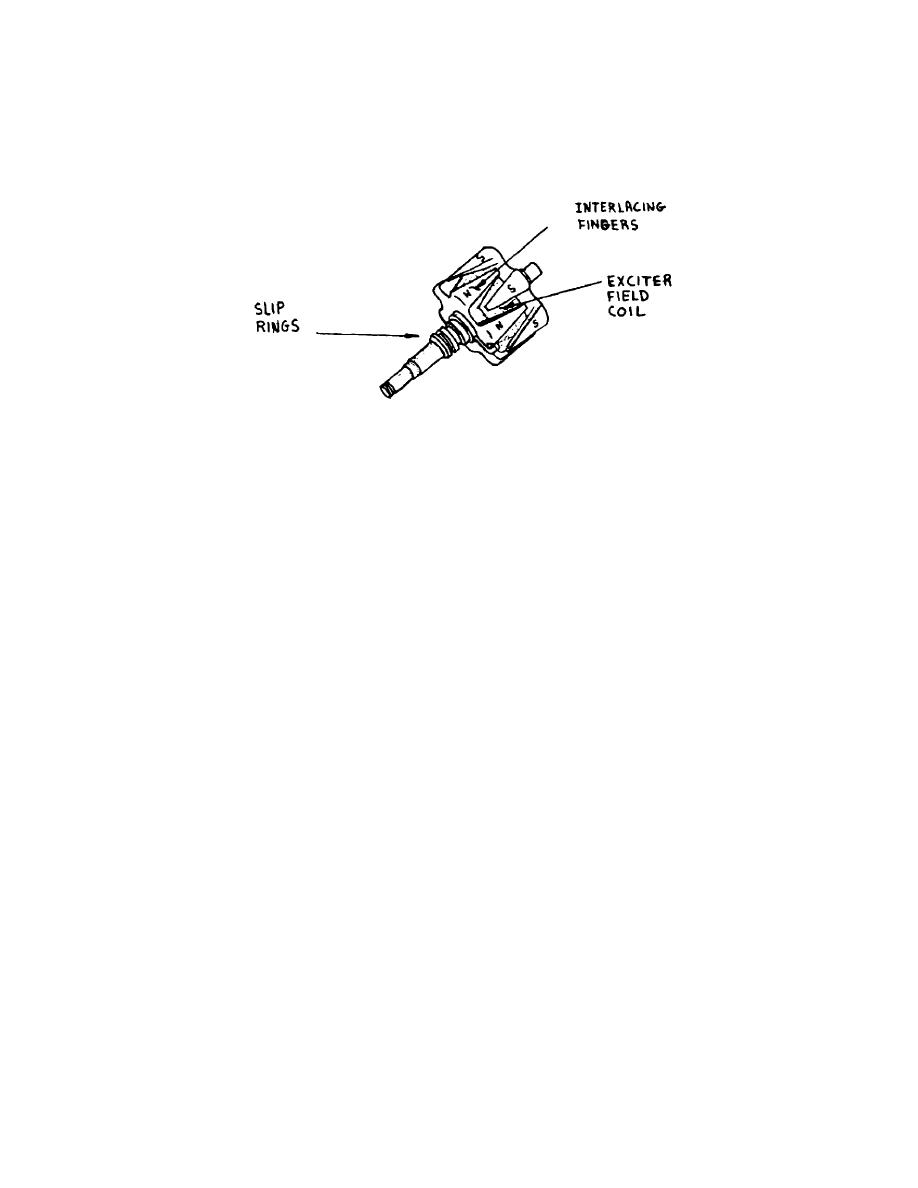
assembly (fig 35A), which houses the exciter field coil, consists of two iron pole
pieces with interlacing fingers. The fingers are mounted over the exciter field
coil, which has many turns of wire. The core is mounted between the iron pieces
and is electrically connected to two sliprings.
Figure 35A.
Rotor assembly.
(1) The coil is energized with current through the brushes making
contact with sliprings. The exciter coil develops the magnetic field; the
intensity of which is controlled by the amount of current supplied to the
sliprings. The magnetic field causes the two iron pole pieces with interlacing
fingers to become magnetized.
(2) The interlaced fingers of the pole pieces produce alternate North
and South poles between the fingers. The rotor shown has a total of 12 poles.
b. The stator assembly consists of three separate windings mounted on a
laminated iron frame. The windings are connected together to form a "Y" or "Delta"
connected stator.
(1) Each winding consists of six coils and each coil contains many turns
of wire. A complete cycle of AC voltage will be generated in each coil as a North
and South pole pass by the coil.
(2) With the six coils in series, each being influenced by a North and
South pole simultaneously, there will be six coil voltages adding together to
provide a complete winding voltage (fig 35B).
(3) Two more identical windings are mounted on the iron frame to
complete the stator assembly. These windings are spaced so that the "Y"-connected
stator delivers three-phase AC voltage.
(4) In paragraph 8 a two-pole magnet type of rotor was used to show that
a complete cycle of AC voltage will be produced for each rotor revolution. With a
12-pole rotor, six complete cycles of AC voltage will be produced for each rotor
revolution.
c. The stator voltage is connected to six diodes which are mounted
internally. They convert the three-phase AC voltage into DC and are arranged as
shown in figure 36.
OS 010, .1-P18


 Previous Page
