d. Also internally mounted is a transistor operated regulator that controls
the output voltage of the generator to the battery.
(1) The output voltage is sensed by the regulator where it is compared
to the voltage reference of a zener diode.
(2) If the output voltage of the generator is higher than the zener
reference voltage, it causes a transistor to turn ON which reduces the exciter
field current. This brings the output voltage down.
(3) If the output voltage of the generator is lower than the zener
reference voltage, it causes a transistor to turn OFF which increases the exciter
field current. This brings the output voltage up since the magnetic flux in the
rotor is increased.
10. LEECE-NEVILLE GENERATOR (OPERATION).
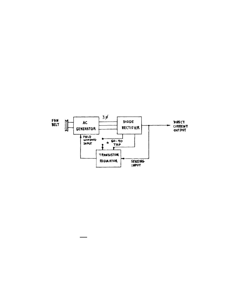
a. Basically, there are three components to be considered in the operation
of the AC charging system: the AC generator, diode rectifier, and transistor
regulator (fig 38). The AC generator is of the revolving field type (the rotor is
the field) so that only two sliprings are needed. The sliprings and brushes are
required to carry only low amperage current to control the exciter field winding
flux on the rotor.
Figure 38.
Block diagram of AC charging system.
(1) The higher the exciter field winding current, the higher the flux
and the higher the three-phase (3) output current and voltage.
(2) If the exciter field winding current is low, this will lower the
three-phase (3) output current and voltage.
b. The six diode rectifiers change the three-phase (3) AC voltage into DC
voltage. This is accomplished by means of silicon diodes that permit the passage
of current in one direction only.
(1) The current capacity is controlled by parallel paths into the
regulator circuit that supplies the exciter field winding with current.
(2) With only one of the paths connected, the current output will have a
40-ampere capability.
(3) With both paths connected to the regulator more current is available
to the field winding through the regulator with a maximum of 60 amperes at the DC
output.
OS 010, 1-P20


 Previous Page
