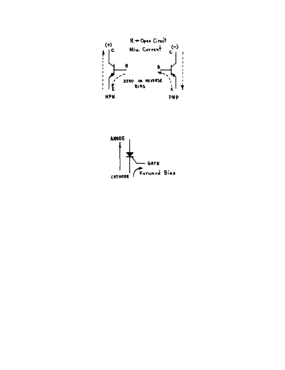
(f) If the diode junction between the emitter and base is reversed
biased, the transistor is said to be OFF and the resistance between the emitter and
collector approaches that of an open circuit (fig 41).
Figure 41.
Transistor OFF.
(2) The silicon controlled rectifier (SCR) is like a conventional diode,
except that it has a gate terminal which controls the rectifying function. The
symbol is shown in figure 42.
Figure 42.
SCR.
(a) With the gate forward bias it operates as a conventional diode
and will rectify.
(b) Once the gate bias has turned ON the SCR, it will remain ON even
if the gate bias is removed, providing there is current between the cathode and
anode.
(c) With no gate bias and current between the cathode and anode, it
will eventually go to zero. When it does, it will turn itself OFF and remain OFF
until the gate is forward biased once again.
(d) To turn the SCR OFF, the current between the cathode and anode
must be interrupted. A large change in the associated circuits is normally
responsible for the SCR's return to an OFF condition.
d. Generators are equipped with internally mounted regulators that control
the output of the generator. The generator, rectifier, and regulator (models
3002AC and 3002AD) are illustrated schematically in figure 43. Operation of the
regulator is as follows:
OS 010, 1-P22


 Previous Page
